Dell OptiPlex Gs Reference and Installation Guide (.pdf) - Page 83
Installing a Drive in the 5.25-Inch Drive Bay, Drive Interface Connectors
 |
View all Dell OptiPlex Gs manuals
Add to My Manuals
Save this manual to your list of manuals |
Page 83 highlights
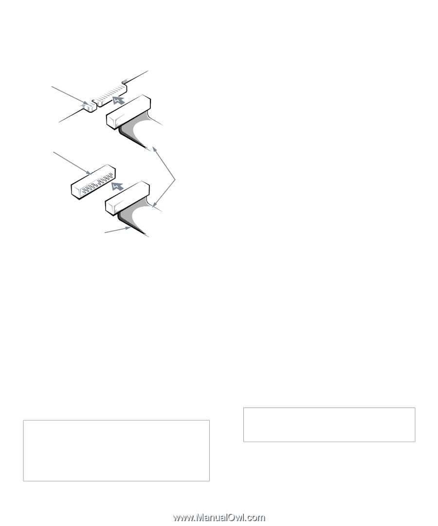
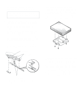
The drive's interface connector is a card-edge connector or a header connector, as shown in Figure 7-5. card-edge connector on drive header connector on drive interface cable colored strip Figure 7-5. Drive Interface Connectors Most interface connectors are keyed for correct insertion; that is, a notch or a missing pin on one connector matches a tab or a filled-in hole on the other connector. Keying ensures that the pin-1 wire in the cable (indicated by the colored strip along one edge of the cable) goes to the pin-1end of the connector on each end. The pin-1end of a card-edge connector is usually identified by a notch cut about a quarter of an inch in from the end of the connector, as shown in Figure 7-5. A header connector is usually keyed by the omission of one of its pins (see Figure 7-5), with the corresponding hole filled in on the connector on the cable. The pin-1 end of a connector on a board or a card is usually indicated by a silk-screened "1" printed directly on the board or card. CAUTION: When connecting an interface cable, do not reverse the interface cable (do not place the colored strip away from pin 1 of the connector). Reversing the cable prevents the drive from operating and could damage the controller, the drive, or both. Installing a Drive in the 5.25-Inch Drive Bay The 5.25-inch drive bay can accommodate any of the following types of drives: • A diskette drive or tape drive that uses the diskette/ tape drive interface on the system board • A CD-ROM or tape drive that uses the secondary EIDE interface on the system board • A CD-ROM or tape drive that uses its own controller card NOTE: For information on configuring, connecting, and installing SCSI drives, see "Installing SCSI Devices" found later in this chapter. To install a drive in this drive bay, follow these steps: 1. Unpack the drive and prepare it for installation. Ground yourself by touching an unpainted metal surface on the back of the computer, and unpack the drive. Check the documentation that accompanied the drive to verify that the drive is configured for your computer system. Change any jumper and switch settings necessary for your configuration. NOTE: If you are installing a non-EIDE tape drive, check the documentation for the drive to determine the jumper or switch settings used to designate the drive as drive address DS4 (not DS2 or DS3 as may be indicated in the drive documentation). Unless the drive is already set to drive 4, reconfigure its jumper or switch setting (see "Jumpers" and "Switches" in Chapter 5). If you are installing an EIDE CD-ROM or EIDE tape drive, configure the drive as a master drive or single drive, depending on the particular drive. 2. Remove the computer cover as instructed in "Removing the Computer Cover" in Chapter 5. CAUTION: See "Protecting Against Electrostatic Discharge" in the safety instructions at the front of this guide. Installing Drives 7-3
-
 1
1 -
2
-
3
-
4
-
5
-
6
-
7
-
8
-
9
-
10
-
11
-
12
-
13
-
14
-
15
-
16
-
17
-
18
-
19
-
20
-
21
-
22
-
23
-
24
-
25
-
26
-
27
-
28
-
29
-
30
-
31
-
32
-
33
-
34
-
35
-
36
-
37
-
38
-
39
-
40
-
41
-
42
-
43
-
44
-
45
-
46
-
47
-
48
-
49
-
50
-
51
-
52
-
53
-
54
-
55
-
56
-
57
-
58
-
59
-
60
-
61
-
62
-
63
-
64
-
65
-
66
-
67
-
68
-
69
-
70
-
71
-
72
-
73
-
74
-
75
-
76
-
77
-
 78
78 -
 79
79 -
 80
80 -
 81
81 -
 82
82 -
 83
83 -
 84
84 -
 85
85 -
 86
86 -
 87
87 -
 88
88 -
89
-
90
-
91
-
92
-
93
-
94
-
95
-
96
-
97
-
98
-
99
-
100
-
101
-
102
-
103
-
104
-
105
-
106
-
107
-
108
-
109
-
110
-
111
-
112
-
113
-
114
-
115
-
116
-
117
-
118
-
119
-
120
-
121
 |
 |