Dell OptiPlex Gs Reference and Installation Guide (.pdf) - Page 88
Removing the Hard-Disk Drive, Bracket, the Bracket
 |
View all Dell OptiPlex Gs manuals
Add to My Manuals
Save this manual to your list of manuals |
Page 88 highlights
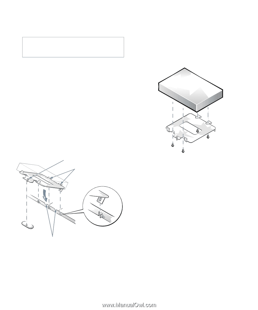
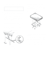
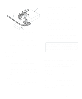
3. Remove the computer cover as instructed in "Removing the Computer Cover" in Chapter 5. CAUTION: See "Protecting Against Electrostatic Discharge" in the safety instructions at the front of this guide. 4. Remove the expansion-card cage as instructed in "Removing the Expansion-Card Cage" in Chapter 5. 5. Remove the hard-disk drive bracket from the chassis. If a hard-disk drive is already attached to the drive bracket and you are replacing it, disconnect the DC power cable and EIDE cable from the drive. Loosen the captive screw that secures the hard-disk drive bracket to the chassis (see Figure 7-12). Then rotate the bracket upward and lift it out of the chassis. To remove the old drive from the bracket, unscrew the four screws securing the drive to the bracket (shown in Figure 7-13). . captive screw tabs on back of drive bracket slots in chassis floor divider Figure 7-12. Removing the Hard-Disk Drive Bracket 6. Secure the drive bracket to the new drive. Turn the drive upside down and locate the four screw holes around its perimeter. Orient the drive bracket so that the end labeled "CONNECTOR" faces the side of the drive containing the interface and power connectors. Place the bracket on the drive and secure it with four screws (see Figure 7-13). Figure 7-13. Securing the Hard-Disk Drive to the Bracket 7. Reinstall the hard-disk drive/bracket assembly in the chassis. Grasp the bracket by the tab containing the captive screw and hold the bracket at a 45-degree angle to the chassis floor. Align the two tabs on the other side of the bracket with the score marks on the chassis floor. Insert the two tabs into the slots in the chassis floor divider, and rotate the assembly downward. Hold the bracket tab containing the captive screw flush with the chassis floor, and then tighten the screw (see Figure 7-12). 7-8 Dell OptiPlex Gs and Gs+ Low-Profile Systems Reference and Installation Guide
-
 1
1 -
2
-
3
-
4
-
5
-
6
-
7
-
8
-
9
-
10
-
11
-
12
-
13
-
14
-
15
-
16
-
17
-
18
-
19
-
20
-
21
-
22
-
23
-
24
-
25
-
26
-
27
-
28
-
29
-
30
-
31
-
32
-
33
-
34
-
35
-
36
-
37
-
38
-
39
-
40
-
41
-
42
-
43
-
44
-
45
-
46
-
47
-
48
-
49
-
50
-
51
-
52
-
53
-
54
-
55
-
56
-
57
-
58
-
59
-
60
-
61
-
62
-
63
-
64
-
65
-
66
-
67
-
68
-
69
-
70
-
71
-
72
-
73
-
74
-
75
-
76
-
77
-
78
-
79
-
80
-
81
-
82
-
 83
83 -
 84
84 -
 85
85 -
 86
86 -
 87
87 -
 88
88 -
 89
89 -
 90
90 -
 91
91 -
 92
92 -
 93
93 -
94
-
95
-
96
-
97
-
98
-
99
-
100
-
101
-
102
-
103
-
104
-
105
-
106
-
107
-
108
-
109
-
110
-
111
-
112
-
113
-
114
-
115
-
116
-
117
-
118
-
119
-
120
-
121
 |
 |