Dell OptiPlex Gs Reference and Installation Guide (.pdf) - Page 73
Performing a Memory Upgrade, Table 6-1., Sample SIMM Configuration, Options
 |
View all Dell OptiPlex Gs manuals
Add to My Manuals
Save this manual to your list of manuals |
Page 73 highlights
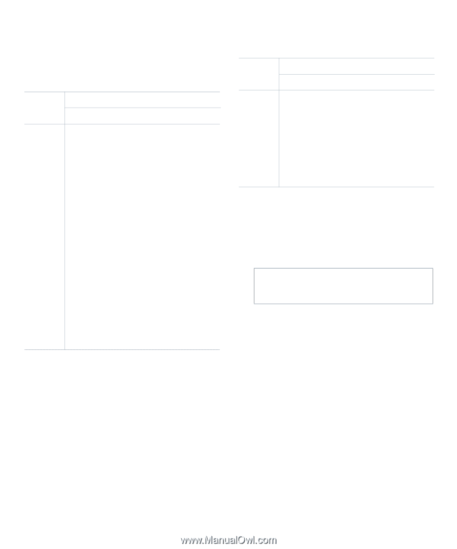
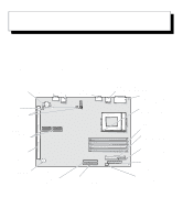
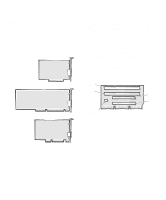
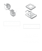
Table 6-1 illustrates these guidelines by listing sample memory configurations and showing valid SIMM combinations and socket placement for each configuration. Table 6-1. Sample SIMM Configuration Options Total SIMM Socket Desired Memory A B C D 8 MB 4 MB 4 MB 16 MB 4 MB 4 MB 4 MB 4 MB 16 MB 8 MB 8 MB 24 MB 8 MB 8 MB 4 MB 4 MB 24 MB 4 MB 4 MB 8 MB 8 MB 32 MB 8 MB 8 MB 8 MB 8 MB 32 MB 16 MB 16 MB 40 MB 4 MB 4 MB 16 MB 16 MB 40 MB 16 MB 16 MB 4 MB 4 MB 48 MB 16 MB 16 MB 8 MB 8 MB 48 MB 8 MB 8 MB 16 MB 16 MB 64 MB 16 MB 16 MB 16 MB 16 MB 64 MB 32 MB 32 MB 72 MB 32 MB 32 MB 4 MB 4 MB Table 6-1. Sample SIMM Configuration Options (Continued) Total SIMM Socket Desired Memory A B C D 72 MB 4 MB 4 MB 32 MB 32 MB 80 MB 8 MB 8 MB 32 MB 32 MB 80 MB 32 MB 32 MB 8 MB 8 MB 96 MB 32 MB 32 MB 16 MB 16 MB 96 MB 16 MB 16 MB 32 MB 32 MB 128 MB 32 MB 32 MB 32 MB 32 MB Performing a Memory Upgrade Follow this procedure to perform a memory upgrade: 1. Remove the computer cover according to the instructions in "Removing the Computer Cover" in Chapter 5. CAUTION: See "Protecting Against Electrostatic Discharge" in the safety instructions at the front of this guide. 2. Determine the SIMM sockets into which you will install SIMMs or replace existing SIMMs. See Table 6-1. 3. Install or replace SIMMs as necessary to reach the desired memory total. Follow the instructions in "Installing a SIMM" or "Removing a SIMM," as appropriate, found later in this section. Installing System Board Options 6-5
-
 1
1 -
2
-
3
-
4
-
5
-
6
-
7
-
8
-
9
-
10
-
11
-
12
-
13
-
14
-
15
-
16
-
17
-
18
-
19
-
20
-
21
-
22
-
23
-
24
-
25
-
26
-
27
-
28
-
29
-
30
-
31
-
32
-
33
-
34
-
35
-
36
-
37
-
38
-
39
-
40
-
41
-
42
-
43
-
44
-
45
-
46
-
47
-
48
-
49
-
50
-
51
-
52
-
53
-
54
-
55
-
56
-
57
-
58
-
59
-
60
-
61
-
62
-
63
-
64
-
65
-
66
-
67
-
 68
68 -
 69
69 -
 70
70 -
 71
71 -
 72
72 -
 73
73 -
 74
74 -
 75
75 -
 76
76 -
 77
77 -
 78
78 -
79
-
80
-
81
-
82
-
83
-
84
-
85
-
86
-
87
-
88
-
89
-
90
-
91
-
92
-
93
-
94
-
95
-
96
-
97
-
98
-
99
-
100
-
101
-
102
-
103
-
104
-
105
-
106
-
107
-
108
-
109
-
110
-
111
-
112
-
113
-
114
-
115
-
116
-
117
-
118
-
119
-
120
-
121
 |
 |