Dell OptiPlex Gs Reference and Installation Guide (.pdf) - Page 78
Upgrading Video Memory, Installing the Heat Sink
 |
View all Dell OptiPlex Gs manuals
Add to My Manuals
Save this manual to your list of manuals |
Page 78 highlights
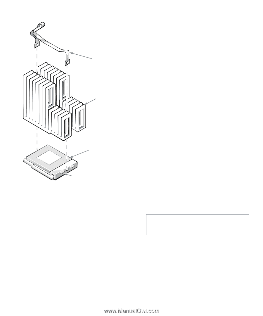
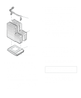
clip heat sink 12. Replace the computer cover, reconnect your computer and peripherals to their power sources, and turn them on. As the system boots, it detects the presence of the new microprocessor and automatically changes the system configuration information in the System Setup program. 13. Enter the System Setup program, and confirm that the MICROPROCESSOR category correctly identifies the installed microprocessor. See Chapter 2, "Using the System Setup Program." 14. Run the Dell diagnostics to verify that the new microprocessor is operating correctly. See your Diagnostics and Troubleshooting Guide for information on running the diskette-based diagnostics and troubleshooting any problems that may occur. microprocessor chip microprocessor socket Figure 6-13. Installing the Heat Sink 10. Replace the microprocessor securing clip. Orient the clip as shown in Figure 6-13, and hook the unfolded end of the clip over the tab on the right edge of the socket. Then press down on the folded end of the clip to snap the clip over the tab on the left edge of the socket. 11. If necessary, change the microprocessor speed jumper setting (see Figure 5-7 to locate system board jumpers). The microprocessor speed jumper should be set for the installed microprocessor's rated internal speed. For example, for a 166-megahertz (MHz) Intel Pentium processor, a jumper plug should be installed on the pins labeled "166." (See "Jumpers" in Chapter 5 for more information.) Upgrading Video Memory You can upgrade video memory from 1 to 2 MB by installing two video-memory upgrade chips. Upgrading the video memory increases video performance and allows you to use video modes for application programs that require high resolutions and many colors. To upgrade the video memory, perform the following steps: 1. Remove the computer cover according to the instructions in "Removing the Computer Cover" in Chapter 5. CAUTION: See "Protecting Against Electrostatic Discharge" in the safety instructions at the front of this guide. 2. To access the video-memory upgrade sockets (labeled "VMEM1" and "VMEM2") on the system board, remove the expansion-card cage as described in "Removing the Expansion-Card Cage" in Chapter 5. 6-10 Dell OptiPlex Gs and Gs+ Low-Profile Systems Reference and Installation Guide
-
 1
1 -
2
-
3
-
4
-
5
-
6
-
7
-
8
-
9
-
10
-
11
-
12
-
13
-
14
-
15
-
16
-
17
-
18
-
19
-
20
-
21
-
22
-
23
-
24
-
25
-
26
-
27
-
28
-
29
-
30
-
31
-
32
-
33
-
34
-
35
-
36
-
37
-
38
-
39
-
40
-
41
-
42
-
43
-
44
-
45
-
46
-
47
-
48
-
49
-
50
-
51
-
52
-
53
-
54
-
55
-
56
-
57
-
58
-
59
-
60
-
61
-
62
-
63
-
64
-
65
-
66
-
67
-
68
-
69
-
70
-
71
-
72
-
 73
73 -
 74
74 -
 75
75 -
 76
76 -
 77
77 -
 78
78 -
 79
79 -
 80
80 -
 81
81 -
 82
82 -
 83
83 -
84
-
85
-
86
-
87
-
88
-
89
-
90
-
91
-
92
-
93
-
94
-
95
-
96
-
97
-
98
-
99
-
100
-
101
-
102
-
103
-
104
-
105
-
106
-
107
-
108
-
109
-
110
-
111
-
112
-
113
-
114
-
115
-
116
-
117
-
118
-
119
-
120
-
121
 |
 |