Dell PowerConnect J-8216 Hardware Guide - Page 120
Installing a Round-Hole Cage Nut Clip Nut
 |
View all Dell PowerConnect J-8216 manuals
Add to My Manuals
Save this manual to your list of manuals |
Page 120 highlights
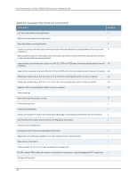
g040637 Dell PowerConnect J-Series J-EX8216 Ethernet Switch Hardware Guide When you install the adjustable mounting brackets, the "arms" of the brackets overlap. The overlap area adjusts the total bracket length to fit three standard rack sizes: 23.62 in. (600 mm), 30 in. (762 mm), and 31.5 in. (800 mm). To install the mounting brackets in a four-post rack (see Figure 39 on page 105 and Figure 40 on page 106): 1. Remove the adjustable mounting brackets from the accessory box. 2. Decide where to position the switch in the rack. If the rack is empty, position the switch in the lowest possible location. See "Rack Requirements for a J-EX8216 Switch" on page 69 and "Cabinet Requirements and Specifications for a J-EX8216 Switch" on page 71. 3. If your rack has unthreaded round or square holes, install 8 cage nuts in the appropriate holes on the left front and left rear rack posts, making sure that the 4 cage nuts on each post are on the same rack level front and back. Use Figure 37 on page 104 or Figure 38 on page 104 to help you with cage-nut installation. Figure 37: Installing a Round-Hole Cage Nut (Clip Nut) Figure 38: Installing a Square-Hole Cage Nut 4. Position the left front adjustable mounting bracket at the desired position in the left side of the rack and line up its front screw holes with the holes in the rack. 5. Use 4 mounting screws appropriate for your rack-plus washers if you installed cage nuts-to attach the left front bracket to the rack. 6. Position one of the rear brackets at the left rear of the rack on the same level as the left front bracket, so that the rear bracket overlaps with the left front bracket. The screw holes for connecting the front and rear brackets should overlap. 7. Use 4 mounting screws appropriate for your rack-plus washers if you installed cage nuts-to attach the left rear bracket to the rack. 104 g040639
-
 1
1 -
2
-
3
-
4
-
5
-
6
-
7
-
8
-
9
-
10
-
11
-
12
-
13
-
14
-
15
-
16
-
17
-
18
-
19
-
20
-
21
-
22
-
23
-
24
-
25
-
26
-
27
-
28
-
29
-
30
-
31
-
32
-
33
-
34
-
35
-
36
-
37
-
38
-
39
-
40
-
41
-
42
-
43
-
44
-
45
-
46
-
47
-
48
-
49
-
50
-
51
-
52
-
53
-
54
-
55
-
56
-
57
-
58
-
59
-
60
-
61
-
62
-
63
-
64
-
65
-
66
-
67
-
68
-
69
-
70
-
71
-
72
-
73
-
74
-
75
-
76
-
77
-
78
-
79
-
80
-
81
-
82
-
83
-
84
-
85
-
86
-
87
-
88
-
89
-
90
-
91
-
92
-
93
-
94
-
95
-
96
-
97
-
98
-
99
-
100
-
101
-
102
-
103
-
104
-
105
-
106
-
107
-
108
-
109
-
110
-
111
-
112
-
113
-
114
-
 115
115 -
 116
116 -
 117
117 -
 118
118 -
 119
119 -
 120
120 -
 121
121 -
 122
122 -
 123
123 -
 124
124 -
 125
125 -
126
-
127
-
128
-
129
-
130
-
131
-
132
-
133
-
134
-
135
-
136
-
137
-
138
-
139
-
140
-
141
-
142
-
143
-
144
-
145
-
146
-
147
-
148
-
149
-
150
-
151
-
152
-
153
-
154
-
155
-
156
-
157
-
158
-
159
-
160
-
161
-
162
-
163
-
164
-
165
-
166
-
167
-
168
-
169
-
170
-
171
-
172
-
173
-
174
-
175
-
176
-
177
-
178
-
179
-
180
-
181
-
182
-
183
-
184
-
185
-
186
-
187
-
188
-
189
-
190
-
191
-
192
-
193
-
194
-
195
-
196
-
197
-
198
-
199
-
200
-
201
-
202
-
203
-
204
-
205
-
206
-
207
-
208
-
209
-
210
-
211
-
212
-
213
-
214
-
215
-
216
-
217
-
218
-
219
-
220
-
221
-
222
-
223
-
224
-
225
-
226
-
227
-
228
-
229
-
230
-
231
-
232
-
233
-
234
-
235
-
236
-
237
-
238
-
239
-
240
-
241
-
242
-
243
-
244
-
245
-
246
-
247
-
248
-
249
-
250
-
251
-
252
-
253
-
254
-
255
-
256
-
257
-
258
-
259
-
260
-
261
-
262
-
263
-
264
-
265
-
266
-
267
-
268
-
269
-
270
 |
 |
