Dell PowerConnect J-8216 Hardware Guide - Page 128
Installing a J-EX8216 Switch in a Four-Post Rack, J-EX Series Switch
 |
View all Dell PowerConnect J-8216 manuals
Add to My Manuals
Save this manual to your list of manuals |
Page 128 highlights
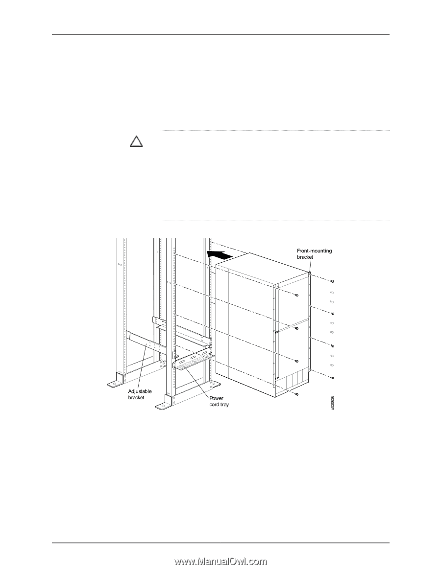
Dell PowerConnect J-Series J-EX8216 Ethernet Switch Hardware Guide 10. Visually inspect the alignment of the switch. If the switch is installed properly in the rack, all the mounting screws on one side of the rack are aligned with the mounting screws on the opposite side and the switch is level. 11. After ensuring that the switch is aligned properly, use the appropriate Phillips (+) screwdriver to tighten the screws to the rack posts. CAUTION: To meet safety and electromagnetic interference (EMI) requirements and to ensure proper operation, you must connect J-EX8200 switches to earth ground before you connect them to power. For installations that require a separate grounding conductor to the chassis, use one of the two protective earthing terminals on the switch chassis to connect to the earth ground. For instructions on connecting a J-EX8200 switch to ground using a separate grounding conductor, see "Connecting Earth Ground to a J-EX Series Switch" on page 129. Figure 47: Installing a J-EX8216 Switch in a Four-Post Rack Related • Removing a J-EX8216 Switch from a Rack or Cabinet on page 152 Documentation • Connecting AC Power to a J-EX8200 Switch on page 131 • Rack Requirements for a J-EX8216 Switch on page 69 • Cabinet Requirements and Specifications for a J-EX8216 Switch on page 71 112
-
 1
1 -
2
-
3
-
4
-
5
-
6
-
7
-
8
-
9
-
10
-
11
-
12
-
13
-
14
-
15
-
16
-
17
-
18
-
19
-
20
-
21
-
22
-
23
-
24
-
25
-
26
-
27
-
28
-
29
-
30
-
31
-
32
-
33
-
34
-
35
-
36
-
37
-
38
-
39
-
40
-
41
-
42
-
43
-
44
-
45
-
46
-
47
-
48
-
49
-
50
-
51
-
52
-
53
-
54
-
55
-
56
-
57
-
58
-
59
-
60
-
61
-
62
-
63
-
64
-
65
-
66
-
67
-
68
-
69
-
70
-
71
-
72
-
73
-
74
-
75
-
76
-
77
-
78
-
79
-
80
-
81
-
82
-
83
-
84
-
85
-
86
-
87
-
88
-
89
-
90
-
91
-
92
-
93
-
94
-
95
-
96
-
97
-
98
-
99
-
100
-
101
-
102
-
103
-
104
-
105
-
106
-
107
-
108
-
109
-
110
-
111
-
112
-
113
-
114
-
115
-
116
-
117
-
118
-
119
-
120
-
121
-
122
-
 123
123 -
 124
124 -
 125
125 -
 126
126 -
 127
127 -
 128
128 -
 129
129 -
 130
130 -
 131
131 -
 132
132 -
 133
133 -
134
-
135
-
136
-
137
-
138
-
139
-
140
-
141
-
142
-
143
-
144
-
145
-
146
-
147
-
148
-
149
-
150
-
151
-
152
-
153
-
154
-
155
-
156
-
157
-
158
-
159
-
160
-
161
-
162
-
163
-
164
-
165
-
166
-
167
-
168
-
169
-
170
-
171
-
172
-
173
-
174
-
175
-
176
-
177
-
178
-
179
-
180
-
181
-
182
-
183
-
184
-
185
-
186
-
187
-
188
-
189
-
190
-
191
-
192
-
193
-
194
-
195
-
196
-
197
-
198
-
199
-
200
-
201
-
202
-
203
-
204
-
205
-
206
-
207
-
208
-
209
-
210
-
211
-
212
-
213
-
214
-
215
-
216
-
217
-
218
-
219
-
220
-
221
-
222
-
223
-
224
-
225
-
226
-
227
-
228
-
229
-
230
-
231
-
232
-
233
-
234
-
235
-
236
-
237
-
238
-
239
-
240
-
241
-
242
-
243
-
244
-
245
-
246
-
247
-
248
-
249
-
250
-
251
-
252
-
253
-
254
-
255
-
256
-
257
-
258
-
259
-
260
-
261
-
262
-
263
-
264
-
265
-
266
-
267
-
268
-
269
-
270
 |
 |