Dell PowerConnect J-8216 Hardware Guide - Page 135

Installing an RE Module in a J-EX8216 Switch
Page 135 highlights

Chapter 9: Installing Switch Components 5. Carefully align the sides of the RE module with the guides inside the chassis. 6. Ensuring that the RE module is correctly aligned, carefully slide it into the chassis until you feel resistance. 7. Push both the ejector levers towards the faceplate of the RE module until the levers are flush against the faceplate and are fully engaged. 8. Tighten the screws, one on each side of the RE module, by turning them clockwise using the Phillips (+) screwdriver, number 2. Ensure that the RE module is fully seated in the chassis. It must be fully seated in order for it to be powered up. 9. Verify that the RE module is installed correctly and functioning normally by checking the LEDs on the faceplate of the RE module. The ON LED and ST LED should be lit steady green a few minutes after the RE module is installed. If the ON LED is unlit, verify that there are enough power supplies installed. See "Calculating Power Requirements for a J-EX8216 Switch" on page 85. If more power supplies are needed, install additional power supplies. See "Installing an AC Power Supply in a J-EX8200 Switch" on page 114. If there are enough power supplies in the switch, remove and install the RE module again. See "Removing an RE Module from a J-EX8216 Switch" on page 163. If the ST LED is lit steady yellow, the RE module has failed. Remove the module and install a new RE module. See "Removing an RE Module from a J-EX8216 Switch" on page 163. Figure 50: Installing an RE Module in a J-EX8216 Switch Related • Routing Engine (RE) Module in a J-EX8216 Switch on page 26 Documentation • RE Module LEDs in a J-EX8216 Switch on page 27 119

  • 1
  • 2
  • 3
  • 4
  • 5
  • 6
  • 7
  • 8
  • 9
  • 10
  • 11
  • 12
  • 13
  • 14
  • 15
  • 16
  • 17
  • 18
  • 19
  • 20
  • 21
  • 22
  • 23
  • 24
  • 25
  • 26
  • 27
  • 28
  • 29
  • 30
  • 31
  • 32
  • 33
  • 34
  • 35
  • 36
  • 37
  • 38
  • 39
  • 40
  • 41
  • 42
  • 43
  • 44
  • 45
  • 46
  • 47
  • 48
  • 49
  • 50
  • 51
  • 52
  • 53
  • 54
  • 55
  • 56
  • 57
  • 58
  • 59
  • 60
  • 61
  • 62
  • 63
  • 64
  • 65
  • 66
  • 67
  • 68
  • 69
  • 70
  • 71
  • 72
  • 73
  • 74
  • 75
  • 76
  • 77
  • 78
  • 79
  • 80
  • 81
  • 82
  • 83
  • 84
  • 85
  • 86
  • 87
  • 88
  • 89
  • 90
  • 91
  • 92
  • 93
  • 94
  • 95
  • 96
  • 97
  • 98
  • 99
  • 100
  • 101
  • 102
  • 103
  • 104
  • 105
  • 106
  • 107
  • 108
  • 109
  • 110
  • 111
  • 112
  • 113
  • 114
  • 115
  • 116
  • 117
  • 118
  • 119
  • 120
  • 121
  • 122
  • 123
  • 124
  • 125
  • 126
  • 127
  • 128
  • 129
  • 130
  • 131
  • 132
  • 133
  • 134
  • 135
  • 136
  • 137
  • 138
  • 139
  • 140
  • 141
  • 142
  • 143
  • 144
  • 145
  • 146
  • 147
  • 148
  • 149
  • 150
  • 151
  • 152
  • 153
  • 154
  • 155
  • 156
  • 157
  • 158
  • 159
  • 160
  • 161
  • 162
  • 163
  • 164
  • 165
  • 166
  • 167
  • 168
  • 169
  • 170
  • 171
  • 172
  • 173
  • 174
  • 175
  • 176
  • 177
  • 178
  • 179
  • 180
  • 181
  • 182
  • 183
  • 184
  • 185
  • 186
  • 187
  • 188
  • 189
  • 190
  • 191
  • 192
  • 193
  • 194
  • 195
  • 196
  • 197
  • 198
  • 199
  • 200
  • 201
  • 202
  • 203
  • 204
  • 205
  • 206
  • 207
  • 208
  • 209
  • 210
  • 211
  • 212
  • 213
  • 214
  • 215
  • 216
  • 217
  • 218
  • 219
  • 220
  • 221
  • 222
  • 223
  • 224
  • 225
  • 226
  • 227
  • 228
  • 229
  • 230
  • 231
  • 232
  • 233
  • 234
  • 235
  • 236
  • 237
  • 238
  • 239
  • 240
  • 241
  • 242
  • 243
  • 244
  • 245
  • 246
  • 247
  • 248
  • 249
  • 250
  • 251
  • 252
  • 253
  • 254
  • 255
  • 256
  • 257
  • 258
  • 259
  • 260
  • 261
  • 262
  • 263
  • 264
  • 265
  • 266
  • 267
  • 268
  • 269
  • 270

5.
Carefully align the sides of the RE module with the guides inside the chassis.
6.
Ensuring that the RE module is correctly aligned, carefully slide it into the chassis until
you feel resistance.
7.
Push both the ejector levers towards the faceplate of the RE module until the levers
are flush against the faceplate and are fully engaged.
8.
Tighten the screws, one on each side of the RE module, by turning them clockwise
using the Phillips (+) screwdriver, number 2. Ensure that the RE module is fully seated
in the chassis. It must be fully seated in order for it to be powered up.
9.
Verify that the RE module is installed correctly and functioning normally by checking
the LEDs on the faceplate of the RE module. The
ON
LED and
ST
LED should be lit
steady green a few minutes after the RE module is installed.
If the
ON
LED is unlit, verify that there are enough power supplies installed. See
“Calculating Power Requirements for a J-EX8216 Switch” on page 85. If more power
supplies are needed, install additional power supplies. See “Installing an AC Power
Supply in a J-EX8200 Switch” on page 114. If there are enough power supplies in the
switch, remove and install the RE module again. See “Removing an RE Module from
a J-EX8216 Switch” on page 163.
If the
ST
LED is lit steady yellow, the RE module has failed. Remove the module and
install a new RE module. See “Removing an RE Module from a J-EX8216 Switch” on
page 163.
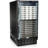
Figure 50: Installing an RE Module in a J-EX8216 Switch
Related
Documentation
Routing Engine (RE) Module in a J-EX8216 Switch on page 26
RE Module LEDs in a J-EX8216 Switch on page 27
119
Chapter 9: Installing Switch Components