Dell PowerConnect J-8216 Hardware Guide - Page 121
Adjustable Mounting Brackets for Four-Post Rack Installation
 |
View all Dell PowerConnect J-8216 manuals
Add to My Manuals
Save this manual to your list of manuals |
Page 121 highlights
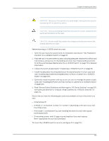
Chapter 8: Installing the Switch 8. Connect left front and rear brackets (see Figure 39 on page 105): a. Insert 6 of the screws provided with the mounting brackets into the overlapping bracket holes. b. Hand tighten the screws fully (to 12-16 in.-lb torque) using a number 2 Phillips screwdriver. Figure 39: Adjustable Mounting Brackets for Four-Post Rack Installation 9. If your rack has unthreaded round or square holes, install 8 cage nuts in the appropriate holes on the right front and right rear rack posts, making sure that the 4 cage nuts on each post are on the same rack level front and back. Use Figure 37 on page 104 or Figure 38 on page 104 to help you with cage-nut installation. 10. Position the right front adjustable mounting bracket at the desired position in the right side of the rack opposite the installed left front bracket, so that it is on the same rack level as the left bracket. If the right and left front brackets are not on the same level, the chassis will rest at an angle in the rack instead of resting flat and level. Line up the right bracket's front screw holes with the holes in the rack. 11. Use 4 mounting screws appropriate for your rack-plus washers if you installed cage nuts-to attach the right front bracket to the rack. 12. Position the other rear bracket at the right rear of the rack on the same level as the right front bracket, so that the rear bracket overlaps with the right front bracket. The screw holes for connecting the front and rear brackets should overlap. 105
-
 1
1 -
2
-
3
-
4
-
5
-
6
-
7
-
8
-
9
-
10
-
11
-
12
-
13
-
14
-
15
-
16
-
17
-
18
-
19
-
20
-
21
-
22
-
23
-
24
-
25
-
26
-
27
-
28
-
29
-
30
-
31
-
32
-
33
-
34
-
35
-
36
-
37
-
38
-
39
-
40
-
41
-
42
-
43
-
44
-
45
-
46
-
47
-
48
-
49
-
50
-
51
-
52
-
53
-
54
-
55
-
56
-
57
-
58
-
59
-
60
-
61
-
62
-
63
-
64
-
65
-
66
-
67
-
68
-
69
-
70
-
71
-
72
-
73
-
74
-
75
-
76
-
77
-
78
-
79
-
80
-
81
-
82
-
83
-
84
-
85
-
86
-
87
-
88
-
89
-
90
-
91
-
92
-
93
-
94
-
95
-
96
-
97
-
98
-
99
-
100
-
101
-
102
-
103
-
104
-
105
-
106
-
107
-
108
-
109
-
110
-
111
-
112
-
113
-
114
-
115
-
 116
116 -
 117
117 -
 118
118 -
 119
119 -
 120
120 -
 121
121 -
 122
122 -
 123
123 -
 124
124 -
 125
125 -
 126
126 -
127
-
128
-
129
-
130
-
131
-
132
-
133
-
134
-
135
-
136
-
137
-
138
-
139
-
140
-
141
-
142
-
143
-
144
-
145
-
146
-
147
-
148
-
149
-
150
-
151
-
152
-
153
-
154
-
155
-
156
-
157
-
158
-
159
-
160
-
161
-
162
-
163
-
164
-
165
-
166
-
167
-
168
-
169
-
170
-
171
-
172
-
173
-
174
-
175
-
176
-
177
-
178
-
179
-
180
-
181
-
182
-
183
-
184
-
185
-
186
-
187
-
188
-
189
-
190
-
191
-
192
-
193
-
194
-
195
-
196
-
197
-
198
-
199
-
200
-
201
-
202
-
203
-
204
-
205
-
206
-
207
-
208
-
209
-
210
-
211
-
212
-
213
-
214
-
215
-
216
-
217
-
218
-
219
-
220
-
221
-
222
-
223
-
224
-
225
-
226
-
227
-
228
-
229
-
230
-
231
-
232
-
233
-
234
-
235
-
236
-
237
-
238
-
239
-
240
-
241
-
242
-
243
-
244
-
245
-
246
-
247
-
248
-
249
-
250
-
251
-
252
-
253
-
254
-
255
-
256
-
257
-
258
-
259
-
260
-
261
-
262
-
263
-
264
-
265
-
266
-
267
-
268
-
269
-
270
 |
 |
