Dell PowerConnect J-8216 Hardware Guide - Page 40

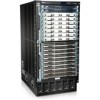
Chassis Status LEDs in a J-EX8200 Switch, Chassis Status LEDs
Page 40 highlights

Dell PowerConnect J-Series J-EX8216 Ethernet Switch Hardware Guide Chassis Status LEDs in a J-EX8200 Switch The top front of the chassis of a J-EX8200 switch has three LEDs on the right side of the LCD panel. See Figure 9 on page 24. Figure 9: Chassis Status LEDs Table 12 on page 24 describes the chassis status LEDs in a J-EX8200 switch, their colors and states, and the status they indicate. You can view the colors of the three LEDs remotely through the CLI by issuing the operational mode command show chassis lcd. Table 12: Chassis Status LEDs in a J-EX8200 Switch LED Label (Description) Color State and Description ALM (Alarm) Unlit No alarm. Red Major alarm. Yellow Minor alarm. SYS (System) Unlit Switch is powered off. Yellow One or more component failures are generating one or more alarms. Green Switch is operating normally. MST (Master) Unlit Switch is powered off. Green Master Routing Engine is operational. A major alarm (red) indicates a critical error condition that requires immediate action. A minor alarm (yellow) indicates a noncritical condition that requires monitoring or maintenance. A minor alarm that is left unchecked might cause interruption in service or performance degradation. All three LEDs can be lit simultaneously. Related • LCD Panel in a J-EX8200 Switch on page 19 Documentation • Understanding Alarm Types and Severity Levels on J-EX Series Switches 24

  • 1
  • 2
  • 3
  • 4
  • 5
  • 6
  • 7
  • 8
  • 9
  • 10
  • 11
  • 12
  • 13
  • 14
  • 15
  • 16
  • 17
  • 18
  • 19
  • 20
  • 21
  • 22
  • 23
  • 24
  • 25
  • 26
  • 27
  • 28
  • 29
  • 30
  • 31
  • 32
  • 33
  • 34
  • 35
  • 36
  • 37
  • 38
  • 39
  • 40
  • 41
  • 42
  • 43
  • 44
  • 45
  • 46
  • 47
  • 48
  • 49
  • 50
  • 51
  • 52
  • 53
  • 54
  • 55
  • 56
  • 57
  • 58
  • 59
  • 60
  • 61
  • 62
  • 63
  • 64
  • 65
  • 66
  • 67
  • 68
  • 69
  • 70
  • 71
  • 72
  • 73
  • 74
  • 75
  • 76
  • 77
  • 78
  • 79
  • 80
  • 81
  • 82
  • 83
  • 84
  • 85
  • 86
  • 87
  • 88
  • 89
  • 90
  • 91
  • 92
  • 93
  • 94
  • 95
  • 96
  • 97
  • 98
  • 99
  • 100
  • 101
  • 102
  • 103
  • 104
  • 105
  • 106
  • 107
  • 108
  • 109
  • 110
  • 111
  • 112
  • 113
  • 114
  • 115
  • 116
  • 117
  • 118
  • 119
  • 120
  • 121
  • 122
  • 123
  • 124
  • 125
  • 126
  • 127
  • 128
  • 129
  • 130
  • 131
  • 132
  • 133
  • 134
  • 135
  • 136
  • 137
  • 138
  • 139
  • 140
  • 141
  • 142
  • 143
  • 144
  • 145
  • 146
  • 147
  • 148
  • 149
  • 150
  • 151
  • 152
  • 153
  • 154
  • 155
  • 156
  • 157
  • 158
  • 159
  • 160
  • 161
  • 162
  • 163
  • 164
  • 165
  • 166
  • 167
  • 168
  • 169
  • 170
  • 171
  • 172
  • 173
  • 174
  • 175
  • 176
  • 177
  • 178
  • 179
  • 180
  • 181
  • 182
  • 183
  • 184
  • 185
  • 186
  • 187
  • 188
  • 189
  • 190
  • 191
  • 192
  • 193
  • 194
  • 195
  • 196
  • 197
  • 198
  • 199
  • 200
  • 201
  • 202
  • 203
  • 204
  • 205
  • 206
  • 207
  • 208
  • 209
  • 210
  • 211
  • 212
  • 213
  • 214
  • 215
  • 216
  • 217
  • 218
  • 219
  • 220
  • 221
  • 222
  • 223
  • 224
  • 225
  • 226
  • 227
  • 228
  • 229
  • 230
  • 231
  • 232
  • 233
  • 234
  • 235
  • 236
  • 237
  • 238
  • 239
  • 240
  • 241
  • 242
  • 243
  • 244
  • 245
  • 246
  • 247
  • 248
  • 249
  • 250
  • 251
  • 252
  • 253
  • 254
  • 255
  • 256
  • 257
  • 258
  • 259
  • 260
  • 261
  • 262
  • 263
  • 264
  • 265
  • 266
  • 267
  • 268
  • 269
  • 270

Chassis Status LEDs in a J-EX8200 Switch
The top front of the chassis of a J-EX8200 switch has three LEDs on the right side of the
LCD panel.
See Figure 9 on page 24.
Figure 9: Chassis Status LEDs
Table 12 on page 24 describes the chassis status LEDs in a J-EX8200 switch, their colors
and states, and the status they indicate. You can view the colors of the three LEDs
remotely through the CLI by issuing the operational mode command
show chassis lcd
.
Table 12: Chassis Status LEDs in a J-EX8200 Switch
State and Description
Color
LED Label (Description)
No alarm.
Unlit
ALM (Alarm)
Major alarm.
Red
Minor alarm.
Yellow
Switch is powered off.
Unlit
SYS (System)
One or more component failures are generating one or more
alarms.
Yellow
Switch is operating normally.
Green
Switch is powered off.
Unlit
MST (Master)
Master Routing Engine is operational.
Green
A major alarm (red) indicates a critical error condition that requires immediate action.
A minor alarm (yellow) indicates a noncritical condition that requires monitoring or
maintenance. A minor alarm that is left unchecked might cause interruption in service or
performance degradation.
All three LEDs can be lit simultaneously.
Related
Documentation
LCD Panel in a J-EX8200 Switch on page 19
Understanding Alarm Types and Severity Levels on J-EX Series Switches
24
Dell PowerConnect J-Series J-EX8216 Ethernet Switch Hardware Guide