Dell PowerConnect J-8216 Hardware Guide - Page 124
Mounting a J-EX8216 Switch on a Rack or Cabinet, Installing a Square-Hole Cage Nut
 |
View all Dell PowerConnect J-8216 manuals
Add to My Manuals
Save this manual to your list of manuals |
Page 124 highlights
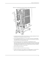
g040639 Dell PowerConnect J-Series J-EX8216 Ethernet Switch Hardware Guide Figure 42: Installing a Square-Hole Cage Nut 4. Position the power cord tray in the rack space immediately below the position where the switch is installed in a four-post rack (see Figure 43 on page 108). Line up the screw holes of the power cord tray with the holes in the rack. Use 4 mounting screws appropriate for your rack-plus washers if you installed cage nuts-to attach the power cord tray to the rack. Figure 43: Installing the Power Cord Tray in a Four-Post Rack Related • Mounting a J-EX8216 Switch on a Rack or Cabinet on page 108 Documentation Mounting a J-EX8216 Switch on a Rack or Cabinet The J-EX8216 switch ships installed with front-mounting brackets on the chassis for mounting the switch on a 19-in. equipment rack or cabinet. (The remainder of this topic uses "rack" to mean "rack or cabinet.") The switch also comes with adjustable mounting brackets to support it in the rack. In a four-post rack, the switch consumes 21 U without the optional power cord tray and 22 U with the optional power cord tray. Installation in a two-post rack is not supported. You can mount two switches on a 42 U four-post rack provided that the rack meets the strength requirements to support the combined weight of the switches. 108
-
 1
1 -
2
-
3
-
4
-
5
-
6
-
7
-
8
-
9
-
10
-
11
-
12
-
13
-
14
-
15
-
16
-
17
-
18
-
19
-
20
-
21
-
22
-
23
-
24
-
25
-
26
-
27
-
28
-
29
-
30
-
31
-
32
-
33
-
34
-
35
-
36
-
37
-
38
-
39
-
40
-
41
-
42
-
43
-
44
-
45
-
46
-
47
-
48
-
49
-
50
-
51
-
52
-
53
-
54
-
55
-
56
-
57
-
58
-
59
-
60
-
61
-
62
-
63
-
64
-
65
-
66
-
67
-
68
-
69
-
70
-
71
-
72
-
73
-
74
-
75
-
76
-
77
-
78
-
79
-
80
-
81
-
82
-
83
-
84
-
85
-
86
-
87
-
88
-
89
-
90
-
91
-
92
-
93
-
94
-
95
-
96
-
97
-
98
-
99
-
100
-
101
-
102
-
103
-
104
-
105
-
106
-
107
-
108
-
109
-
110
-
111
-
112
-
113
-
114
-
115
-
116
-
117
-
118
-
 119
119 -
 120
120 -
 121
121 -
 122
122 -
 123
123 -
 124
124 -
 125
125 -
 126
126 -
 127
127 -
 128
128 -
 129
129 -
130
-
131
-
132
-
133
-
134
-
135
-
136
-
137
-
138
-
139
-
140
-
141
-
142
-
143
-
144
-
145
-
146
-
147
-
148
-
149
-
150
-
151
-
152
-
153
-
154
-
155
-
156
-
157
-
158
-
159
-
160
-
161
-
162
-
163
-
164
-
165
-
166
-
167
-
168
-
169
-
170
-
171
-
172
-
173
-
174
-
175
-
176
-
177
-
178
-
179
-
180
-
181
-
182
-
183
-
184
-
185
-
186
-
187
-
188
-
189
-
190
-
191
-
192
-
193
-
194
-
195
-
196
-
197
-
198
-
199
-
200
-
201
-
202
-
203
-
204
-
205
-
206
-
207
-
208
-
209
-
210
-
211
-
212
-
213
-
214
-
215
-
216
-
217
-
218
-
219
-
220
-
221
-
222
-
223
-
224
-
225
-
226
-
227
-
228
-
229
-
230
-
231
-
232
-
233
-
234
-
235
-
236
-
237
-
238
-
239
-
240
-
241
-
242
-
243
-
244
-
245
-
246
-
247
-
248
-
249
-
250
-
251
-
252
-
253
-
254
-
255
-
256
-
257
-
258
-
259
-
260
-
261
-
262
-
263
-
264
-
265
-
266
-
267
-
268
-
269
-
270
 |
 |
