Dell PowerConnect J-8216 Hardware Guide - Page 47

SF Module LEDs in a J-EX8216 Switch
Page 47 highlights

Chapter 2: Component Descriptions The SF modules contain logic that determines which RE module is the master. The master RE module controls many internal functions of the SF modules. The SF modules provide these functions: • Provide data path connectivity for the switch (switch data between line cards) Each SF module has these components: • SF module LEDs-Indicate system status. See "SF Module LEDs in a J-EX8216 Switch" on page 31. • Ejector levers-Used for installing and removing the SF module. • Handle-Facilitates installing and removing the SF module. • Captive screws-Secure the SF module in place. Related • Installing an SF Module in a J-EX8216 Switch on page 120 Documentation • Removing an SF Module from a J-EX8216 Switch on page 165 SF Module LEDs in a J-EX8216 Switch Each Switch Fabric (SF) module has two LEDs on the top of the module's front panel. See Figure 14 on page 31. Figure 14: SF Module LEDs in a J-EX8216 Switch Table 17 on page 32 describes these LEDs, their colors and states, and the status they indicate. 31

  • 1
  • 2
  • 3
  • 4
  • 5
  • 6
  • 7
  • 8
  • 9
  • 10
  • 11
  • 12
  • 13
  • 14
  • 15
  • 16
  • 17
  • 18
  • 19
  • 20
  • 21
  • 22
  • 23
  • 24
  • 25
  • 26
  • 27
  • 28
  • 29
  • 30
  • 31
  • 32
  • 33
  • 34
  • 35
  • 36
  • 37
  • 38
  • 39
  • 40
  • 41
  • 42
  • 43
  • 44
  • 45
  • 46
  • 47
  • 48
  • 49
  • 50
  • 51
  • 52
  • 53
  • 54
  • 55
  • 56
  • 57
  • 58
  • 59
  • 60
  • 61
  • 62
  • 63
  • 64
  • 65
  • 66
  • 67
  • 68
  • 69
  • 70
  • 71
  • 72
  • 73
  • 74
  • 75
  • 76
  • 77
  • 78
  • 79
  • 80
  • 81
  • 82
  • 83
  • 84
  • 85
  • 86
  • 87
  • 88
  • 89
  • 90
  • 91
  • 92
  • 93
  • 94
  • 95
  • 96
  • 97
  • 98
  • 99
  • 100
  • 101
  • 102
  • 103
  • 104
  • 105
  • 106
  • 107
  • 108
  • 109
  • 110
  • 111
  • 112
  • 113
  • 114
  • 115
  • 116
  • 117
  • 118
  • 119
  • 120
  • 121
  • 122
  • 123
  • 124
  • 125
  • 126
  • 127
  • 128
  • 129
  • 130
  • 131
  • 132
  • 133
  • 134
  • 135
  • 136
  • 137
  • 138
  • 139
  • 140
  • 141
  • 142
  • 143
  • 144
  • 145
  • 146
  • 147
  • 148
  • 149
  • 150
  • 151
  • 152
  • 153
  • 154
  • 155
  • 156
  • 157
  • 158
  • 159
  • 160
  • 161
  • 162
  • 163
  • 164
  • 165
  • 166
  • 167
  • 168
  • 169
  • 170
  • 171
  • 172
  • 173
  • 174
  • 175
  • 176
  • 177
  • 178
  • 179
  • 180
  • 181
  • 182
  • 183
  • 184
  • 185
  • 186
  • 187
  • 188
  • 189
  • 190
  • 191
  • 192
  • 193
  • 194
  • 195
  • 196
  • 197
  • 198
  • 199
  • 200
  • 201
  • 202
  • 203
  • 204
  • 205
  • 206
  • 207
  • 208
  • 209
  • 210
  • 211
  • 212
  • 213
  • 214
  • 215
  • 216
  • 217
  • 218
  • 219
  • 220
  • 221
  • 222
  • 223
  • 224
  • 225
  • 226
  • 227
  • 228
  • 229
  • 230
  • 231
  • 232
  • 233
  • 234
  • 235
  • 236
  • 237
  • 238
  • 239
  • 240
  • 241
  • 242
  • 243
  • 244
  • 245
  • 246
  • 247
  • 248
  • 249
  • 250
  • 251
  • 252
  • 253
  • 254
  • 255
  • 256
  • 257
  • 258
  • 259
  • 260
  • 261
  • 262
  • 263
  • 264
  • 265
  • 266
  • 267
  • 268
  • 269
  • 270

The SF modules contain logic that determines which RE module is the master. The master
RE module controls many internal functions of the SF modules.
The SF modules provide these functions:
Provide data path connectivity for the switch (switch data between line cards)
Each SF module has these components:
SF module LEDs—Indicate system status. See “SF Module LEDs in a J-EX8216 Switch”
on page 31.
Ejector levers—Used for installing and removing the SF module.
Handle—Facilitates installing and removing the SF module.
Captive screws—Secure the SF module in place.
Related
Documentation
Installing an SF Module in a J-EX8216 Switch on page 120
Removing an SF Module from a J-EX8216 Switch on page 165
SF Module LEDs in a J-EX8216 Switch
Each Switch Fabric (SF) module has two LEDs on the top of the module’s front panel.
See Figure 14 on page 31.
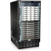
Figure 14: SF Module LEDs in a J-EX8216 Switch
Table 17 on page 32 describes these LEDs, their colors and states, and the status they
indicate.
31
Chapter 2: Component Descriptions