Dell PowerConnect J-8216 Hardware Guide - Page 125
see Installing Adjustable Mounting Brackets in a Rack or Cabinet for a J-EX8200
 |
View all Dell PowerConnect J-8216 manuals
Add to My Manuals
Save this manual to your list of manuals |
Page 125 highlights
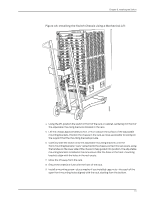
Chapter 8: Installing the Switch WARNING: Because of the switch's size and weight, we require the use of a mechanical lift to install the switch. CAUTION: If you are installing more than one switch in a rack, install the first switch at the bottom of the rack. CAUTION: Do not install line cards in the chassis until after you mount the chassis securely on a rack. Before mounting a J-EX8216 switch on a rack: 1. Verify the site meets the requirements for installation described in "Site Preparation Checklist for a J-EX8200 Switch" on page 63. 2. Place the rack in its permanent location, allowing adequate clearance for airflow and maintenance, and secure it to the building structure. See "Clearance Requirements for Airflow and Hardware Maintenance for a J-EX8216 Switch" on page 73 for detailed information. 3. Unpack the switch as described in "Unpacking a J-EX8200 Switch" on page 98. 4. Install the adjustable mounting brackets at the desired position in a four-post rack (see "Installing Adjustable Mounting Brackets in a Rack or Cabinet for a J-EX8200 Switch" on page 103). 5. Optionally, install the power cord tray, so you can use it to manage the power supply cords (see "Installing the Power Cord Tray in a Rack or Cabinet for a J-EX8200 Switch" on page 106). 6. Read "General Safety Guidelines and Warnings for J-EX Series Switches" on page 201, with particular attention to "Chassis Lifting Guidelines for J-EX8200 Switches" on page 214. Ensure that you have the following parts and tools available to mount the switch on a rack: • A mechanical lift • A Phillips (+) screwdriver, number 2 or number 3, depending on the size of your rack mounting screws • A flat-blade (-) screwdriver if you are installing the switch in a rack with square, nonthreaded holes • 20 mounting screws-and 20 cage nuts and washers if your rack requires them-appropriate for your rack (provided) To mount the J-EX8216 switch on a rack (see Figure 47 on page 112): 109
-
 1
1 -
2
-
3
-
4
-
5
-
6
-
7
-
8
-
9
-
10
-
11
-
12
-
13
-
14
-
15
-
16
-
17
-
18
-
19
-
20
-
21
-
22
-
23
-
24
-
25
-
26
-
27
-
28
-
29
-
30
-
31
-
32
-
33
-
34
-
35
-
36
-
37
-
38
-
39
-
40
-
41
-
42
-
43
-
44
-
45
-
46
-
47
-
48
-
49
-
50
-
51
-
52
-
53
-
54
-
55
-
56
-
57
-
58
-
59
-
60
-
61
-
62
-
63
-
64
-
65
-
66
-
67
-
68
-
69
-
70
-
71
-
72
-
73
-
74
-
75
-
76
-
77
-
78
-
79
-
80
-
81
-
82
-
83
-
84
-
85
-
86
-
87
-
88
-
89
-
90
-
91
-
92
-
93
-
94
-
95
-
96
-
97
-
98
-
99
-
100
-
101
-
102
-
103
-
104
-
105
-
106
-
107
-
108
-
109
-
110
-
111
-
112
-
113
-
114
-
115
-
116
-
117
-
118
-
119
-
 120
120 -
 121
121 -
 122
122 -
 123
123 -
 124
124 -
 125
125 -
 126
126 -
 127
127 -
 128
128 -
 129
129 -
 130
130 -
131
-
132
-
133
-
134
-
135
-
136
-
137
-
138
-
139
-
140
-
141
-
142
-
143
-
144
-
145
-
146
-
147
-
148
-
149
-
150
-
151
-
152
-
153
-
154
-
155
-
156
-
157
-
158
-
159
-
160
-
161
-
162
-
163
-
164
-
165
-
166
-
167
-
168
-
169
-
170
-
171
-
172
-
173
-
174
-
175
-
176
-
177
-
178
-
179
-
180
-
181
-
182
-
183
-
184
-
185
-
186
-
187
-
188
-
189
-
190
-
191
-
192
-
193
-
194
-
195
-
196
-
197
-
198
-
199
-
200
-
201
-
202
-
203
-
204
-
205
-
206
-
207
-
208
-
209
-
210
-
211
-
212
-
213
-
214
-
215
-
216
-
217
-
218
-
219
-
220
-
221
-
222
-
223
-
224
-
225
-
226
-
227
-
228
-
229
-
230
-
231
-
232
-
233
-
234
-
235
-
236
-
237
-
238
-
239
-
240
-
241
-
242
-
243
-
244
-
245
-
246
-
247
-
248
-
249
-
250
-
251
-
252
-
253
-
254
-
255
-
256
-
257
-
258
-
259
-
260
-
261
-
262
-
263
-
264
-
265
-
266
-
267
-
268
-
269
-
270
 |
 |
