Dell PowerConnect J-8216 Hardware Guide - Page 141

Installing a Line Card in a J-EX8200 Switch Chassis
Page 141 highlights

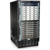
Chapter 9: Installing Switch Components 4. Grasp the ejector levers on the faceplate of the line card and pull them outward until they are fully open. CAUTION: Before you slide the line card into the slot on the switch chassis, ensure the line card is aligned correctly. Misalignment might cause the pins to bend, making the line card unusable. 5. Place one hand around the faceplate of the line card and the other hand under the line card to support it. CAUTION: The line cards in J-EX8200 switches weigh more than 10 lb (4.5 kg). Be prepared to accept the full weight as you slide the line card into the chassis. 6. Lift the line card, and position it in the chassis with the faceplate facing you and the sides of the line card aligned with the guides in the line card slot on the switch chassis. 7. Using both hands, gently slide the line card into the slot until it is fully seated. NOTE: You might need to lift the line card slightly to seat it correctly in the slot. 8. Grasp the ejector levers on the line card and push them inward simultaneously until the line card is fully seated. When the ON LED turns green, the line card is ready for use. CAUTION: After the ON LED turns green, wait for at least 30 seconds before installing another line card or removing a line card. 9. Tighten the captive screws on the faceplate of the line card by using the screwdriver. Figure 54: Installing a Line Card in a J-EX8200 Switch Chassis You can verify that the line card is functioning correctly by issuing the show chassis fpc and show chassis fpc pic-status commands. 125

  • 1
  • 2
  • 3
  • 4
  • 5
  • 6
  • 7
  • 8
  • 9
  • 10
  • 11
  • 12
  • 13
  • 14
  • 15
  • 16
  • 17
  • 18
  • 19
  • 20
  • 21
  • 22
  • 23
  • 24
  • 25
  • 26
  • 27
  • 28
  • 29
  • 30
  • 31
  • 32
  • 33
  • 34
  • 35
  • 36
  • 37
  • 38
  • 39
  • 40
  • 41
  • 42
  • 43
  • 44
  • 45
  • 46
  • 47
  • 48
  • 49
  • 50
  • 51
  • 52
  • 53
  • 54
  • 55
  • 56
  • 57
  • 58
  • 59
  • 60
  • 61
  • 62
  • 63
  • 64
  • 65
  • 66
  • 67
  • 68
  • 69
  • 70
  • 71
  • 72
  • 73
  • 74
  • 75
  • 76
  • 77
  • 78
  • 79
  • 80
  • 81
  • 82
  • 83
  • 84
  • 85
  • 86
  • 87
  • 88
  • 89
  • 90
  • 91
  • 92
  • 93
  • 94
  • 95
  • 96
  • 97
  • 98
  • 99
  • 100
  • 101
  • 102
  • 103
  • 104
  • 105
  • 106
  • 107
  • 108
  • 109
  • 110
  • 111
  • 112
  • 113
  • 114
  • 115
  • 116
  • 117
  • 118
  • 119
  • 120
  • 121
  • 122
  • 123
  • 124
  • 125
  • 126
  • 127
  • 128
  • 129
  • 130
  • 131
  • 132
  • 133
  • 134
  • 135
  • 136
  • 137
  • 138
  • 139
  • 140
  • 141
  • 142
  • 143
  • 144
  • 145
  • 146
  • 147
  • 148
  • 149
  • 150
  • 151
  • 152
  • 153
  • 154
  • 155
  • 156
  • 157
  • 158
  • 159
  • 160
  • 161
  • 162
  • 163
  • 164
  • 165
  • 166
  • 167
  • 168
  • 169
  • 170
  • 171
  • 172
  • 173
  • 174
  • 175
  • 176
  • 177
  • 178
  • 179
  • 180
  • 181
  • 182
  • 183
  • 184
  • 185
  • 186
  • 187
  • 188
  • 189
  • 190
  • 191
  • 192
  • 193
  • 194
  • 195
  • 196
  • 197
  • 198
  • 199
  • 200
  • 201
  • 202
  • 203
  • 204
  • 205
  • 206
  • 207
  • 208
  • 209
  • 210
  • 211
  • 212
  • 213
  • 214
  • 215
  • 216
  • 217
  • 218
  • 219
  • 220
  • 221
  • 222
  • 223
  • 224
  • 225
  • 226
  • 227
  • 228
  • 229
  • 230
  • 231
  • 232
  • 233
  • 234
  • 235
  • 236
  • 237
  • 238
  • 239
  • 240
  • 241
  • 242
  • 243
  • 244
  • 245
  • 246
  • 247
  • 248
  • 249
  • 250
  • 251
  • 252
  • 253
  • 254
  • 255
  • 256
  • 257
  • 258
  • 259
  • 260
  • 261
  • 262
  • 263
  • 264
  • 265
  • 266
  • 267
  • 268
  • 269
  • 270

4.
Grasp the ejector levers on the faceplate of the line card and pull them outward until
they are fully open.
CAUTION:
Before you slide the line card into the slot on the switch chassis,
ensure the line card is aligned correctly. Misalignment might cause the
pins to bend, making the line card unusable.
5.
Place one hand around the faceplate of the line card and the other hand under the
line card to support it.
CAUTION:
The line cards in J-EX8200 switches weigh more than 10 lb
(4.5 kg). Be prepared to accept the full weight as you slide the line card
into the chassis.
6.
Lift the line card, and position it in the chassis with the faceplate facing you and the
sides of the line card aligned with the guides in the line card slot on the switch chassis.
7.
Using both hands, gently slide the line card into the slot until it is fully seated.
NOTE:
You might need to lift the line card slightly to seat it correctly in
the slot.
8.
Grasp the ejector levers on the line card and push them inward simultaneously until
the line card is fully seated. When the
ON
LED turns green, the line card is ready for
use.
CAUTION:
After the
ON
LED turns green, wait for at least 30 seconds
before installing another line card or removing a line card.
9.
Tighten the captive screws on the faceplate of the line card by using the screwdriver.
Figure 54: Installing a Line Card in a J-EX8200 Switch Chassis
You can verify that the line card is functioning correctly by issuing the
show chassis fpc
and
show chassis fpc pic-status
commands.
125
Chapter 9: Installing Switch Components