Dell PowerConnect J-8216 Hardware Guide - Page 62

Airflow Through the J-EX8216 Switch Chassis, rear is located on the front of the chassis
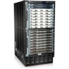
Page 62 highlights

Dell PowerConnect J-Series J-EX8216 Ethernet Switch Hardware Guide Figure 28: Airflow Through the J-EX8216 Switch Chassis The air intake to cool the power supplies is located in the front of each power supply unit. The exhaust for the hot air collected from the power supplies is located on the rear of the chassis at the bottom. See the side view in Figure 28 on page 46 for this airflow. Cooling for the rear of the chassis and the Switch Fabric (SF) modules is done with front-to-side airflow. The air intake to cool the chassis from the midplane to the chassis rear is located on the front of the chassis, just below the slots for the power supplies. Air is pulled in from the chassis front towards the chassis rear and then pulled to the top of the chassis by the top fan tray. The hot air is then forced to turn left and exhausts from the left side of the chassis. See Figure 29 on page 47 for this airflow. 46

  • 1
  • 2
  • 3
  • 4
  • 5
  • 6
  • 7
  • 8
  • 9
  • 10
  • 11
  • 12
  • 13
  • 14
  • 15
  • 16
  • 17
  • 18
  • 19
  • 20
  • 21
  • 22
  • 23
  • 24
  • 25
  • 26
  • 27
  • 28
  • 29
  • 30
  • 31
  • 32
  • 33
  • 34
  • 35
  • 36
  • 37
  • 38
  • 39
  • 40
  • 41
  • 42
  • 43
  • 44
  • 45
  • 46
  • 47
  • 48
  • 49
  • 50
  • 51
  • 52
  • 53
  • 54
  • 55
  • 56
  • 57
  • 58
  • 59
  • 60
  • 61
  • 62
  • 63
  • 64
  • 65
  • 66
  • 67
  • 68
  • 69
  • 70
  • 71
  • 72
  • 73
  • 74
  • 75
  • 76
  • 77
  • 78
  • 79
  • 80
  • 81
  • 82
  • 83
  • 84
  • 85
  • 86
  • 87
  • 88
  • 89
  • 90
  • 91
  • 92
  • 93
  • 94
  • 95
  • 96
  • 97
  • 98
  • 99
  • 100
  • 101
  • 102
  • 103
  • 104
  • 105
  • 106
  • 107
  • 108
  • 109
  • 110
  • 111
  • 112
  • 113
  • 114
  • 115
  • 116
  • 117
  • 118
  • 119
  • 120
  • 121
  • 122
  • 123
  • 124
  • 125
  • 126
  • 127
  • 128
  • 129
  • 130
  • 131
  • 132
  • 133
  • 134
  • 135
  • 136
  • 137
  • 138
  • 139
  • 140
  • 141
  • 142
  • 143
  • 144
  • 145
  • 146
  • 147
  • 148
  • 149
  • 150
  • 151
  • 152
  • 153
  • 154
  • 155
  • 156
  • 157
  • 158
  • 159
  • 160
  • 161
  • 162
  • 163
  • 164
  • 165
  • 166
  • 167
  • 168
  • 169
  • 170
  • 171
  • 172
  • 173
  • 174
  • 175
  • 176
  • 177
  • 178
  • 179
  • 180
  • 181
  • 182
  • 183
  • 184
  • 185
  • 186
  • 187
  • 188
  • 189
  • 190
  • 191
  • 192
  • 193
  • 194
  • 195
  • 196
  • 197
  • 198
  • 199
  • 200
  • 201
  • 202
  • 203
  • 204
  • 205
  • 206
  • 207
  • 208
  • 209
  • 210
  • 211
  • 212
  • 213
  • 214
  • 215
  • 216
  • 217
  • 218
  • 219
  • 220
  • 221
  • 222
  • 223
  • 224
  • 225
  • 226
  • 227
  • 228
  • 229
  • 230
  • 231
  • 232
  • 233
  • 234
  • 235
  • 236
  • 237
  • 238
  • 239
  • 240
  • 241
  • 242
  • 243
  • 244
  • 245
  • 246
  • 247
  • 248
  • 249
  • 250
  • 251
  • 252
  • 253
  • 254
  • 255
  • 256
  • 257
  • 258
  • 259
  • 260
  • 261
  • 262
  • 263
  • 264
  • 265
  • 266
  • 267
  • 268
  • 269
  • 270

Figure 28: Airflow Through the J-EX8216 Switch Chassis
The air intake to cool the power supplies is located in the front of each power supply unit.
The exhaust for the hot air collected from the power supplies is located on the rear of
the chassis at the bottom. See the side view in Figure 28 on page 46 for this airflow.
Cooling for the rear of the chassis and the Switch Fabric (SF) modules is done with
front-to-side airflow. The air intake to cool the chassis from the midplane to the chassis
rear is located on the front of the chassis, just below the slots for the power supplies. Air
is pulled in from the chassis front towards the chassis rear and then pulled to the top of
the chassis by the top fan tray. The hot air is then forced to turn left and exhausts from
the left side of the chassis. See Figure 29 on page 47 for this airflow.
46
Dell PowerConnect J-Series J-EX8216 Ethernet Switch Hardware Guide