Dell PowerConnect J-8216 Hardware Guide - Page 63

Airflow for the J-EX8216 Switch Chassis Rear, range, 32°F 0°C through 104°F 40°C.
Page 63 highlights

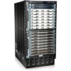
Chapter 2: Component Descriptions Figure 29: Airflow for the J-EX8216 Switch Chassis Rear NOTE: Do not block the air intake below the power supply slots. The Routing Engine (RE) module monitors the temperature of switch components. Under normal operating conditions, the fans in the fan trays run at less than full speed. Each fan tray has two fan tray controllers. In each fan tray, the fans are numbered 1 through 9. Fans 1 through 5 are controlled by the first fan tray controller. Fans 6 through 9 are controlled by the second fan tray controller. If one fan tray controller fails, the other fan tray controller keeps the remaining fans in the fan tray working. This allows the switch to continue to operate normally as long as the remaining working fans cool the chassis sufficiently. If the ambient temperature rises above the threshold 113°F (45°C), the speed of the working fans is automatically adjusted to keep the temperature within the acceptable range, 32°F (0°C) through 104°F (40°C). 47

  • 1
  • 2
  • 3
  • 4
  • 5
  • 6
  • 7
  • 8
  • 9
  • 10
  • 11
  • 12
  • 13
  • 14
  • 15
  • 16
  • 17
  • 18
  • 19
  • 20
  • 21
  • 22
  • 23
  • 24
  • 25
  • 26
  • 27
  • 28
  • 29
  • 30
  • 31
  • 32
  • 33
  • 34
  • 35
  • 36
  • 37
  • 38
  • 39
  • 40
  • 41
  • 42
  • 43
  • 44
  • 45
  • 46
  • 47
  • 48
  • 49
  • 50
  • 51
  • 52
  • 53
  • 54
  • 55
  • 56
  • 57
  • 58
  • 59
  • 60
  • 61
  • 62
  • 63
  • 64
  • 65
  • 66
  • 67
  • 68
  • 69
  • 70
  • 71
  • 72
  • 73
  • 74
  • 75
  • 76
  • 77
  • 78
  • 79
  • 80
  • 81
  • 82
  • 83
  • 84
  • 85
  • 86
  • 87
  • 88
  • 89
  • 90
  • 91
  • 92
  • 93
  • 94
  • 95
  • 96
  • 97
  • 98
  • 99
  • 100
  • 101
  • 102
  • 103
  • 104
  • 105
  • 106
  • 107
  • 108
  • 109
  • 110
  • 111
  • 112
  • 113
  • 114
  • 115
  • 116
  • 117
  • 118
  • 119
  • 120
  • 121
  • 122
  • 123
  • 124
  • 125
  • 126
  • 127
  • 128
  • 129
  • 130
  • 131
  • 132
  • 133
  • 134
  • 135
  • 136
  • 137
  • 138
  • 139
  • 140
  • 141
  • 142
  • 143
  • 144
  • 145
  • 146
  • 147
  • 148
  • 149
  • 150
  • 151
  • 152
  • 153
  • 154
  • 155
  • 156
  • 157
  • 158
  • 159
  • 160
  • 161
  • 162
  • 163
  • 164
  • 165
  • 166
  • 167
  • 168
  • 169
  • 170
  • 171
  • 172
  • 173
  • 174
  • 175
  • 176
  • 177
  • 178
  • 179
  • 180
  • 181
  • 182
  • 183
  • 184
  • 185
  • 186
  • 187
  • 188
  • 189
  • 190
  • 191
  • 192
  • 193
  • 194
  • 195
  • 196
  • 197
  • 198
  • 199
  • 200
  • 201
  • 202
  • 203
  • 204
  • 205
  • 206
  • 207
  • 208
  • 209
  • 210
  • 211
  • 212
  • 213
  • 214
  • 215
  • 216
  • 217
  • 218
  • 219
  • 220
  • 221
  • 222
  • 223
  • 224
  • 225
  • 226
  • 227
  • 228
  • 229
  • 230
  • 231
  • 232
  • 233
  • 234
  • 235
  • 236
  • 237
  • 238
  • 239
  • 240
  • 241
  • 242
  • 243
  • 244
  • 245
  • 246
  • 247
  • 248
  • 249
  • 250
  • 251
  • 252
  • 253
  • 254
  • 255
  • 256
  • 257
  • 258
  • 259
  • 260
  • 261
  • 262
  • 263
  • 264
  • 265
  • 266
  • 267
  • 268
  • 269
  • 270

Figure 29: Airflow for the J-EX8216 Switch Chassis Rear
NOTE:
Do not block the air intake below the power supply slots.
The Routing Engine (RE) module monitors the temperature of switch components. Under
normal operating conditions, the fans in the fan trays run at less than full speed. Each
fan tray has two fan tray controllers.
In each fan tray, the fans are numbered 1 through 9. Fans 1 through 5 are controlled by
the first fan tray controller. Fans 6 through 9 are controlled by the second fan tray
controller. If one fan tray controller fails, the other fan tray controller keeps the remaining
fans in the fan tray working. This allows the switch to continue to operate normally as
long as the remaining working fans cool the chassis sufficiently.
If the ambient temperature rises above the threshold 113°F (45°C), the speed of the
working fans is automatically adjusted to keep the temperature within the acceptable
range, 32°F (0°C) through 104°F (40°C).
47
Chapter 2: Component Descriptions