Dell PowerConnect J-8216 Hardware Guide - Page 123
Installing a Round-Hole Cage Nut Clip Nut
 |
View all Dell PowerConnect J-8216 manuals
Add to My Manuals
Save this manual to your list of manuals |
Page 123 highlights
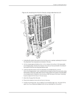
Chapter 8: Installing the Switch The power cord tray uses 1 U of rack space, so the total space occupied by a J-EX8216 switch chassis and power cord tray is 22 U. Ensure that you have the following tools and parts available to install the power cord tray: • A Phillips (+) screwdriver, number 1, 2, or 3, depending on the size of your rack mounting screws • A flat-blade (-) screwdriver if you are installing the power cord tray in a rack with square, nonthreaded holes • 4 mounting screws-and 4 cage nuts and washers if your rack requires them-of the appropriate size to attach the power cord tray to the rack To install the power cord tray (see Figure 43 on page 108): 1. Remove the power cord tray from the accessory box. 2. Decide where to position the switch in the rack. If the rack is empty, choose the lowest possible location. See "Rack Requirements for a J-EX8216 Switch" on page 69 and "Cabinet Requirements and Specifications for a J-EX8216 Switch" on page 71. NOTE: Installation of a J-EX8216 switch in a two-post rack is not supported. 3. If your rack has unthreaded round or square holes, install 4 cage nuts in the appropriate holes on the right and left front rack posts, making sure that the 2 cage nuts on each post are on the same rack level front and back. Use Figure 41 on page 107 or Figure 42 on page 108 to help you with cage-nut installation. Figure 41: Installing a Round-Hole Cage Nut (Clip Nut) 107 g040637
-
 1
1 -
2
-
3
-
4
-
5
-
6
-
7
-
8
-
9
-
10
-
11
-
12
-
13
-
14
-
15
-
16
-
17
-
18
-
19
-
20
-
21
-
22
-
23
-
24
-
25
-
26
-
27
-
28
-
29
-
30
-
31
-
32
-
33
-
34
-
35
-
36
-
37
-
38
-
39
-
40
-
41
-
42
-
43
-
44
-
45
-
46
-
47
-
48
-
49
-
50
-
51
-
52
-
53
-
54
-
55
-
56
-
57
-
58
-
59
-
60
-
61
-
62
-
63
-
64
-
65
-
66
-
67
-
68
-
69
-
70
-
71
-
72
-
73
-
74
-
75
-
76
-
77
-
78
-
79
-
80
-
81
-
82
-
83
-
84
-
85
-
86
-
87
-
88
-
89
-
90
-
91
-
92
-
93
-
94
-
95
-
96
-
97
-
98
-
99
-
100
-
101
-
102
-
103
-
104
-
105
-
106
-
107
-
108
-
109
-
110
-
111
-
112
-
113
-
114
-
115
-
116
-
117
-
 118
118 -
 119
119 -
 120
120 -
 121
121 -
 122
122 -
 123
123 -
 124
124 -
 125
125 -
 126
126 -
 127
127 -
 128
128 -
129
-
130
-
131
-
132
-
133
-
134
-
135
-
136
-
137
-
138
-
139
-
140
-
141
-
142
-
143
-
144
-
145
-
146
-
147
-
148
-
149
-
150
-
151
-
152
-
153
-
154
-
155
-
156
-
157
-
158
-
159
-
160
-
161
-
162
-
163
-
164
-
165
-
166
-
167
-
168
-
169
-
170
-
171
-
172
-
173
-
174
-
175
-
176
-
177
-
178
-
179
-
180
-
181
-
182
-
183
-
184
-
185
-
186
-
187
-
188
-
189
-
190
-
191
-
192
-
193
-
194
-
195
-
196
-
197
-
198
-
199
-
200
-
201
-
202
-
203
-
204
-
205
-
206
-
207
-
208
-
209
-
210
-
211
-
212
-
213
-
214
-
215
-
216
-
217
-
218
-
219
-
220
-
221
-
222
-
223
-
224
-
225
-
226
-
227
-
228
-
229
-
230
-
231
-
232
-
233
-
234
-
235
-
236
-
237
-
238
-
239
-
240
-
241
-
242
-
243
-
244
-
245
-
246
-
247
-
248
-
249
-
250
-
251
-
252
-
253
-
254
-
255
-
256
-
257
-
258
-
259
-
260
-
261
-
262
-
263
-
264
-
265
-
266
-
267
-
268
-
269
-
270
 |
 |
