Dell PowerEdge SC440 Hardware Owner's Manual - Page 103
System Board Connectors
 |
View all Dell PowerEdge SC440 manuals
Add to My Manuals
Save this manual to your list of manuals |
Page 103 highlights
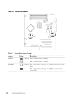
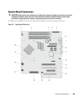
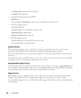
System Board Connectors CAUTION: Only trained service technicians are authorized to remove the system cover and access any of the components inside the system. See your Product Information Guide for complete information about safety precautions, working inside the computer, and protecting against electrostatic discharge. See Figure 6-2 and Table 6-2 for the location and description of the system board connectors. Figure 6-2. System Board Connectors 1 2 34 5 6 7 20 8 19 9 10 18 11 12 17 13 16 15 14 Jumpers and Connectors 103
-
 1
1 -
2
-
3
-
4
-
5
-
6
-
7
-
8
-
9
-
10
-
11
-
12
-
13
-
14
-
15
-
16
-
17
-
18
-
19
-
20
-
21
-
22
-
23
-
24
-
25
-
26
-
27
-
28
-
29
-
30
-
31
-
32
-
33
-
34
-
35
-
36
-
37
-
38
-
39
-
40
-
41
-
42
-
43
-
44
-
45
-
46
-
47
-
48
-
49
-
50
-
51
-
52
-
53
-
54
-
55
-
56
-
57
-
58
-
59
-
60
-
61
-
62
-
63
-
64
-
65
-
66
-
67
-
68
-
69
-
70
-
71
-
72
-
73
-
74
-
75
-
76
-
77
-
78
-
79
-
80
-
81
-
82
-
83
-
84
-
85
-
86
-
87
-
88
-
89
-
90
-
91
-
92
-
93
-
94
-
95
-
96
-
97
-
 98
98 -
 99
99 -
 100
100 -
 101
101 -
 102
102 -
 103
103 -
 104
104 -
 105
105 -
 106
106 -
 107
107 -
 108
108 -
109
-
110
-
111
-
112
-
113
-
114
-
115
-
116
-
117
-
118
-
119
-
120
-
121
-
122
-
123
-
124
-
125
-
126
-
127
-
128
-
129
-
130
-
131
-
132
-
133
-
134
-
135
-
136
-
137
-
138
-
139
-
140
-
141
-
142
-
143
-
144
 |
 |

Jumpers and Connectors
103
System Board Connectors
CAUTION:
Only trained service technicians are authorized to remove the system cover and access any of the
components inside the system. See your
Product Information Guide
for complete information about safety
precautions, working inside the computer, and protecting against electrostatic discharge.
See Figure 6-2 and Table 6-2 for the location and description of the system board connectors.
Figure 6-2.
System Board Connectors
8
6
1
9
2
20
3
4
5
7
10
14
15
11
12
13
16
18
17
19