Dell PowerEdge SC440 Hardware Owner's Manual - Page 11
Front-Panel Features and Indicators, shows the controls, indicators - hard drive
 |
View all Dell PowerEdge SC440 manuals
Add to My Manuals
Save this manual to your list of manuals |
Page 11 highlights
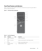
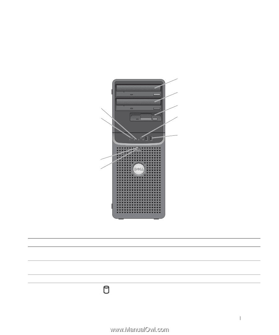
Front-Panel Features and Indicators Figure 1-1 shows the controls, indicators, and connectors located on the system's front panel. Table 1-2 provides component descriptions. Figure 1-1. Front-Panel Features and Indicators 1 2 9 3 8 4 5 7 6 Table 1-2. Front-Panel Components Item Component Icon 1 upper 5.25-inch drive bay 2 lower 5.25-inch drive bay 3 flex bay 4 hard-drive activity indicator Description Holds an optical drive. Holds an optional optical or tape backup unit drive. Holds an optional diskette drive. Indicates hard drive activity. About Your System 11
-
 1
1 -
2
-
3
-
4
-
5
-
 6
6 -
 7
7 -
 8
8 -
 9
9 -
 10
10 -
 11
11 -
 12
12 -
 13
13 -
 14
14 -
 15
15 -
 16
16 -
17
-
18
-
19
-
20
-
21
-
22
-
23
-
24
-
25
-
26
-
27
-
28
-
29
-
30
-
31
-
32
-
33
-
34
-
35
-
36
-
37
-
38
-
39
-
40
-
41
-
42
-
43
-
44
-
45
-
46
-
47
-
48
-
49
-
50
-
51
-
52
-
53
-
54
-
55
-
56
-
57
-
58
-
59
-
60
-
61
-
62
-
63
-
64
-
65
-
66
-
67
-
68
-
69
-
70
-
71
-
72
-
73
-
74
-
75
-
76
-
77
-
78
-
79
-
80
-
81
-
82
-
83
-
84
-
85
-
86
-
87
-
88
-
89
-
90
-
91
-
92
-
93
-
94
-
95
-
96
-
97
-
98
-
99
-
100
-
101
-
102
-
103
-
104
-
105
-
106
-
107
-
108
-
109
-
110
-
111
-
112
-
113
-
114
-
115
-
116
-
117
-
118
-
119
-
120
-
121
-
122
-
123
-
124
-
125
-
126
-
127
-
128
-
129
-
130
-
131
-
132
-
133
-
134
-
135
-
136
-
137
-
138
-
139
-
140
-
141
-
142
-
143
-
144
 |
 |
About Your System
11
Front-Panel Features and Indicators
Figure 1-1 shows the controls, indicators, and connectors located on the system's front panel. Table 1-2
provides component descriptions.
Figure 1-1.
Front-Panel Features and Indicators
1
2
3
4
6
7
8
9
5
Table 1-2.
Front-Panel Components
Item
Component
Icon
Description
1
upper 5.25-inch drive
bay
Holds an optical drive.
2
lower 5.25-inch drive
bay
Holds an optional optical or tape backup unit drive.
3
flex bay
Holds an optional diskette drive.
4
hard-drive activity
indicator
Indicates hard drive activity.