Dell PowerEdge SC440 Hardware Owner's Manual - Page 104
Disabling a Forgotten Password, Open the system. See Opening the System
 |
View all Dell PowerEdge SC440 manuals
Add to My Manuals
Save this manual to your list of manuals |
Page 104 highlights
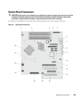
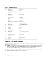
Table 6-2. System Board Connectors Item Connector Description 1 12VPOWER power 2 DIMM_1, DIMM_2, DIMM_3, memory modules DIMM_4 3 BATTERY battery socket 4 FAN_MEM memory fan 5 FRONTPANEL front panel 6 POWER main power 7 IDE IDE drive 8 SATA0, SATA1, SATA2, SATA3 SATA drives 9 RTCRST RTC reset jumper 10 INTRUDER chassis intrusion header 11 SLOT1 PCIe x1 12 SLOT2 PCIe x8 13 SLOT4 PCIe x4 14 SLOT3, SLOT5 PCI 15 AUX_LED auxiliary hard-drive LED 16 FLOPPY diskette drive 17 FAN_CARD_CAGE card cage fan 18 FAN_CPU processor fan 19 PSWD password jumper 20 CPU processor Disabling a Forgotten Password The password jumper on the system board enables the system password features or disables them and clears any password(s) currently in use. CAUTION: Only trained service technicians are authorized to remove the system cover and access any of the components inside the system. See your Product Information Guide for complete information about safety precautions, working inside the computer, and protecting against electrostatic discharge. 1 Turn off the system and attached peripherals, and disconnect the system from the electrical outlet. 2 Open the system. See "Opening the System" on page 41. 104 Jumpers and Connectors
-
 1
1 -
2
-
3
-
4
-
5
-
6
-
7
-
8
-
9
-
10
-
11
-
12
-
13
-
14
-
15
-
16
-
17
-
18
-
19
-
20
-
21
-
22
-
23
-
24
-
25
-
26
-
27
-
28
-
29
-
30
-
31
-
32
-
33
-
34
-
35
-
36
-
37
-
38
-
39
-
40
-
41
-
42
-
43
-
44
-
45
-
46
-
47
-
48
-
49
-
50
-
51
-
52
-
53
-
54
-
55
-
56
-
57
-
58
-
59
-
60
-
61
-
62
-
63
-
64
-
65
-
66
-
67
-
68
-
69
-
70
-
71
-
72
-
73
-
74
-
75
-
76
-
77
-
78
-
79
-
80
-
81
-
82
-
83
-
84
-
85
-
86
-
87
-
88
-
89
-
90
-
91
-
92
-
93
-
94
-
95
-
96
-
97
-
98
-
 99
99 -
 100
100 -
 101
101 -
 102
102 -
 103
103 -
 104
104 -
 105
105 -
 106
106 -
 107
107 -
 108
108 -
 109
109 -
110
-
111
-
112
-
113
-
114
-
115
-
116
-
117
-
118
-
119
-
120
-
121
-
122
-
123
-
124
-
125
-
126
-
127
-
128
-
129
-
130
-
131
-
132
-
133
-
134
-
135
-
136
-
137
-
138
-
139
-
140
-
141
-
142
-
143
-
144
 |
 |