Dell PowerEdge SC440 Hardware Owner's Manual - Page 12
Table 1-2., Front-Panel Components, Component, Description, See Diagnostic Lights
 |
View all Dell PowerEdge SC440 manuals
Add to My Manuals
Save this manual to your list of manuals |
Page 12 highlights
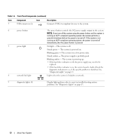
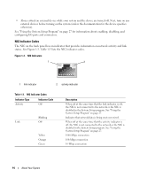
Table 1-2. Front-Panel Components (continued) Item Component Icon 5 USB connectors (2) Description Connects USB 2.0-compliant devices to the system. 6 power button 7 power light 8 network link light The power button controls the DC power supply output to the system. NOTE: If you turn off the system using the power button and the system is running an ACPI-compliant operating system, the system performs a graceful shutdown before the power is turned off. If the system is not running an ACPI-compliant operating system, the power is turned off immediately after the power button is pressed. No light - The system is off. Steady green - The system is powered on. Blinking green - The system is in a low power state. Steady amber - The power supply is probably good. Blinking amber - The system is powering up. • If the hard drive indicator is off, the power supply may need to be replaced. • If the hard drive indicator is on, the system board is faulty. Check the diagnostic indicators to see if the specific problem is identified. See "Diagnostic Lights" on page 15. Lights when the system is linked to a network. 9 diagnostic lights (4) Display light-pattern codes to assist in troubleshooting system problems. See "Diagnostic Lights" on page 15. 12 About Your System
-
 1
1 -
2
-
3
-
4
-
5
-
6
-
 7
7 -
 8
8 -
 9
9 -
 10
10 -
 11
11 -
 12
12 -
 13
13 -
 14
14 -
 15
15 -
 16
16 -
 17
17 -
18
-
19
-
20
-
21
-
22
-
23
-
24
-
25
-
26
-
27
-
28
-
29
-
30
-
31
-
32
-
33
-
34
-
35
-
36
-
37
-
38
-
39
-
40
-
41
-
42
-
43
-
44
-
45
-
46
-
47
-
48
-
49
-
50
-
51
-
52
-
53
-
54
-
55
-
56
-
57
-
58
-
59
-
60
-
61
-
62
-
63
-
64
-
65
-
66
-
67
-
68
-
69
-
70
-
71
-
72
-
73
-
74
-
75
-
76
-
77
-
78
-
79
-
80
-
81
-
82
-
83
-
84
-
85
-
86
-
87
-
88
-
89
-
90
-
91
-
92
-
93
-
94
-
95
-
96
-
97
-
98
-
99
-
100
-
101
-
102
-
103
-
104
-
105
-
106
-
107
-
108
-
109
-
110
-
111
-
112
-
113
-
114
-
115
-
116
-
117
-
118
-
119
-
120
-
121
-
122
-
123
-
124
-
125
-
126
-
127
-
128
-
129
-
130
-
131
-
132
-
133
-
134
-
135
-
136
-
137
-
138
-
139
-
140
-
141
-
142
-
143
-
144
 |
 |