Dell PowerEdge SC440 Hardware Owner's Manual - Page 15
Power Supply Indicators, Diagnostic Lights - bios
 |
View all Dell PowerEdge SC440 manuals
Add to My Manuals
Save this manual to your list of manuals |
Page 15 highlights
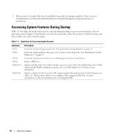
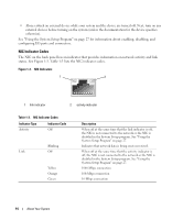
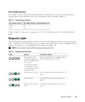
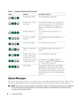
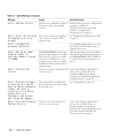
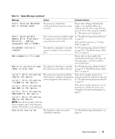
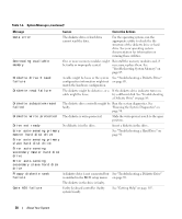
Power Supply Indicators The voltage selection switch on the back panel of the system allows you to select one of two primary voltage inputs. Ensure that the switch is set to the proper voltage according to Table 1-4. Table 1-4. Voltage Selection Switch If your power source is: The voltage selection switch should be set to: 110 V 115 220 V 230 For information on system power requirements, see "Technical Specifications" in your Getting Started Guide. Diagnostic Lights The four diagnostic indicator lights on the system front panel display error codes during system startup. Table 1-5 lists the causes and possible corrective actions associated with these codes. A highlighted circle indicates the light is on; a non-highlighted circle indicates the light is off. NOTE: Once the system completes POST, all diagnostic lights will be OFF. Table 1-5. Diagnostic Indicator Codes Code Causes Corrective Action The computer is in a Plug the computer into a working electrical normal off condition or a outlet and press the power button. possible pre-BIOS failure has occurred. The diagnostic lights are not lit after the system successfully boots to the operating system. Possible processor failure. See "Troubleshooting the Microprocessor" on page 95. Memory failure. See "Troubleshooting System Memory" on page 87. Possible expansion card See "Troubleshooting Expansion Cards" on failure. page 93. About Your System 15
-
 1
1 -
2
-
3
-
4
-
5
-
6
-
7
-
8
-
9
-
 10
10 -
 11
11 -
 12
12 -
 13
13 -
 14
14 -
 15
15 -
 16
16 -
 17
17 -
 18
18 -
 19
19 -
 20
20 -
21
-
22
-
23
-
24
-
25
-
26
-
27
-
28
-
29
-
30
-
31
-
32
-
33
-
34
-
35
-
36
-
37
-
38
-
39
-
40
-
41
-
42
-
43
-
44
-
45
-
46
-
47
-
48
-
49
-
50
-
51
-
52
-
53
-
54
-
55
-
56
-
57
-
58
-
59
-
60
-
61
-
62
-
63
-
64
-
65
-
66
-
67
-
68
-
69
-
70
-
71
-
72
-
73
-
74
-
75
-
76
-
77
-
78
-
79
-
80
-
81
-
82
-
83
-
84
-
85
-
86
-
87
-
88
-
89
-
90
-
91
-
92
-
93
-
94
-
95
-
96
-
97
-
98
-
99
-
100
-
101
-
102
-
103
-
104
-
105
-
106
-
107
-
108
-
109
-
110
-
111
-
112
-
113
-
114
-
115
-
116
-
117
-
118
-
119
-
120
-
121
-
122
-
123
-
124
-
125
-
126
-
127
-
128
-
129
-
130
-
131
-
132
-
133
-
134
-
135
-
136
-
137
-
138
-
139
-
140
-
141
-
142
-
143
-
144
 |
 |
