Dell PowerEdge SC440 Hardware Owner's Manual - Page 45
Installing a Diskette Drive, Turn off the system and attached peripherals
 |
View all Dell PowerEdge SC440 manuals
Add to My Manuals
Save this manual to your list of manuals |
Page 45 highlights
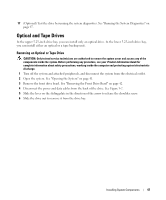
Figure 3-5. Removing or Installing a Diskette Drive 4 3 5 2 1 6 1 arrow on the sliding plate 4 power cable to diskette drive (P7) 2 sliding plate 5 data cable to diskette drive 3 drive-stop tab 6 data cable to system board connector (FLOPPY) 7 If you are permanently removing the drive, replace the 3.5-inch insert on front drive bezel. See "Replacing an Insert on the Front Drive Bezel" on page 44. If you are replacing the diskette drive, see "Installing a Diskette Drive" on page 45. 8 Replace the front drive bezel. See "Replacing the Front Drive Bezel" on page 43. 9 Close the system. See "Closing the System" on page 41. 10 Reconnect the system to the electrical outlet, and turn on the system and attached peripherals. Installing a Diskette Drive CAUTION: Only trained service technicians are authorized to remove the system cover and access any of the components inside the system. Before performing any procedure, see your Product Information Guide for complete information about safety precautions, working inside the computer and protecting against electrostatic discharge. 1 Turn off the system and attached peripherals, and disconnect the system from the electrical outlet. 2 Open the system. See "Opening the System" on page 41. Installing System Components 45
-
 1
1 -
2
-
3
-
4
-
5
-
6
-
7
-
8
-
9
-
10
-
11
-
12
-
13
-
14
-
15
-
16
-
17
-
18
-
19
-
20
-
21
-
22
-
23
-
24
-
25
-
26
-
27
-
28
-
29
-
30
-
31
-
32
-
33
-
34
-
35
-
36
-
37
-
38
-
39
-
 40
40 -
 41
41 -
 42
42 -
 43
43 -
 44
44 -
 45
45 -
 46
46 -
 47
47 -
 48
48 -
 49
49 -
 50
50 -
51
-
52
-
53
-
54
-
55
-
56
-
57
-
58
-
59
-
60
-
61
-
62
-
63
-
64
-
65
-
66
-
67
-
68
-
69
-
70
-
71
-
72
-
73
-
74
-
75
-
76
-
77
-
78
-
79
-
80
-
81
-
82
-
83
-
84
-
85
-
86
-
87
-
88
-
89
-
90
-
91
-
92
-
93
-
94
-
95
-
96
-
97
-
98
-
99
-
100
-
101
-
102
-
103
-
104
-
105
-
106
-
107
-
108
-
109
-
110
-
111
-
112
-
113
-
114
-
115
-
116
-
117
-
118
-
119
-
120
-
121
-
122
-
123
-
124
-
125
-
126
-
127
-
128
-
129
-
130
-
131
-
132
-
133
-
134
-
135
-
136
-
137
-
138
-
139
-
140
-
141
-
142
-
143
-
144
 |
 |
