Dell PowerEdge SC440 Hardware Owner's Manual - Page 61
See System, Memory Info
 |
View all Dell PowerEdge SC440 manuals
Add to My Manuals
Save this manual to your list of manuals |
Page 61 highlights
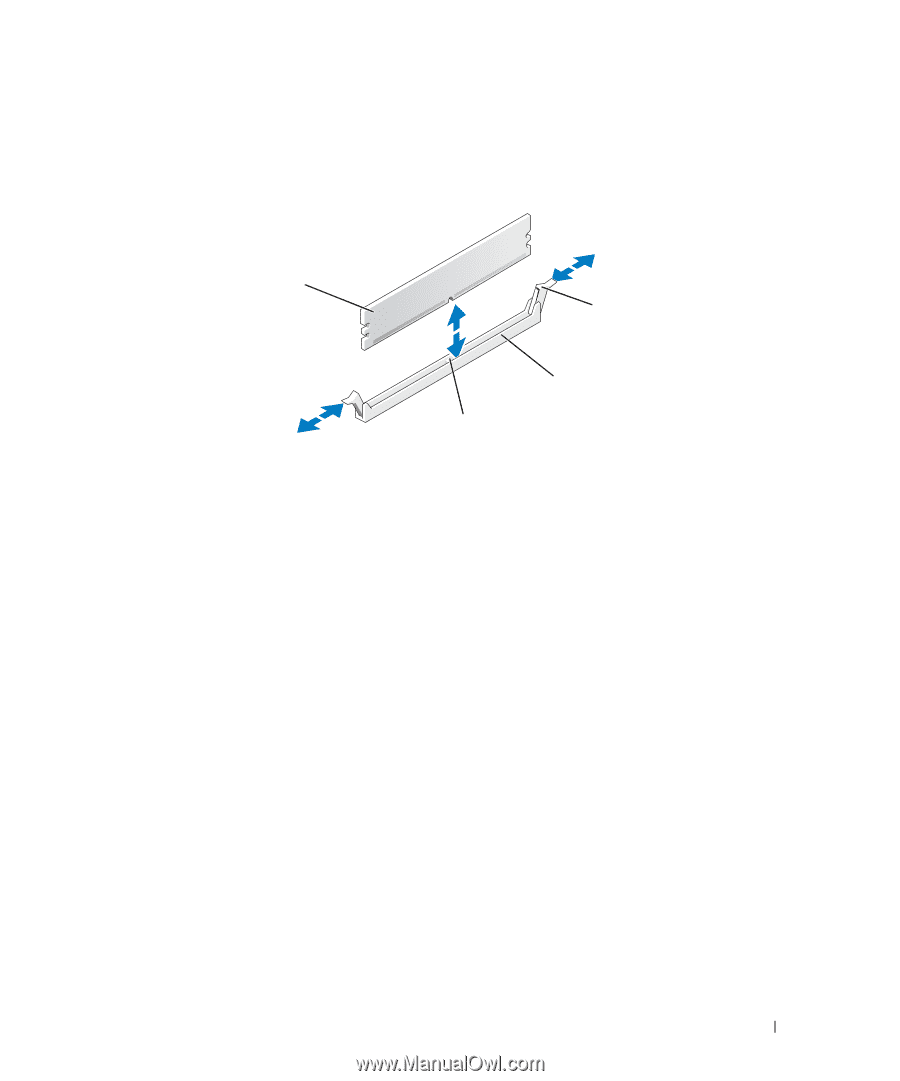
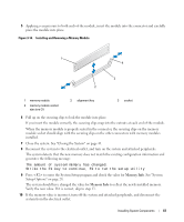
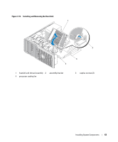
5 Applying even pressure to both ends of the module, insert the module into the connector and carefully press the module into place. Figure 3-14. Installing and Removing a Memory Module 1 4 3 2 1 memory module 4 memory module socket ejectors (2) 2 alignment key 3 socket 6 Pull up on the securing clips to lock the module into place. If you insert the module correctly, the securing clips snap into the cutouts at each end of the module. When the memory module is properly seated in the connector, the securing clips on the memory module socket should align with the securing clips on the other connectors with memory modules installed. 7 Close the system. See "Closing the System" on page 41. 8 Reconnect the system to the electrical outlet, and turn on the system and attached peripherals. The system detects that the new memory does not match the existing configuration information and generates the following message: The amount of system memory has changed. Strike the F1 key to continue, F2 to run the setup utility 9 Press to enter the System Setup program and check the value for Memory Info. See "System Setup Options" on page 28. The system should have changed the value for Memory Info to reflect the newly installed memory. Verify the new value. If it is correct, skip to step 13. 10 If the memory value is incorrect, turn off the system and attached peripherals, and disconnect the system from the electrical outlet. Installing System Components 61
-
 1
1 -
2
-
3
-
4
-
5
-
6
-
7
-
8
-
9
-
10
-
11
-
12
-
13
-
14
-
15
-
16
-
17
-
18
-
19
-
20
-
21
-
22
-
23
-
24
-
25
-
26
-
27
-
28
-
29
-
30
-
31
-
32
-
33
-
34
-
35
-
36
-
37
-
38
-
39
-
40
-
41
-
42
-
43
-
44
-
45
-
46
-
47
-
48
-
49
-
50
-
51
-
52
-
53
-
54
-
55
-
 56
56 -
 57
57 -
 58
58 -
 59
59 -
 60
60 -
 61
61 -
 62
62 -
 63
63 -
 64
64 -
 65
65 -
 66
66 -
67
-
68
-
69
-
70
-
71
-
72
-
73
-
74
-
75
-
76
-
77
-
78
-
79
-
80
-
81
-
82
-
83
-
84
-
85
-
86
-
87
-
88
-
89
-
90
-
91
-
92
-
93
-
94
-
95
-
96
-
97
-
98
-
99
-
100
-
101
-
102
-
103
-
104
-
105
-
106
-
107
-
108
-
109
-
110
-
111
-
112
-
113
-
114
-
115
-
116
-
117
-
118
-
119
-
120
-
121
-
122
-
123
-
124
-
125
-
126
-
127
-
128
-
129
-
130
-
131
-
132
-
133
-
134
-
135
-
136
-
137
-
138
-
139
-
140
-
141
-
142
-
143
-
144
 |
 |