Dell PowerEdge SC440 Hardware Owner's Manual - Page 77
CAUTION, NOTICE, Remove the processor. See Removing the Processor
 |
View all Dell PowerEdge SC440 manuals
Add to My Manuals
Save this manual to your list of manuals |
Page 77 highlights
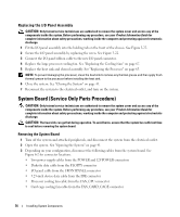
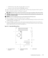
• SATA hard-drive data cable(s) from the SATA connector(s) • Intrusion switch cable from the INTRUDER connector 4 Remove all expansion cards and any attached cables. See "Removing an Expansion Card" on page 56. 5 Remove all memory modules. See "Memory" on page 58. NOTE: Record the memory-module socket locations to ensure proper reinstallation of the memory modules. CAUTION: The processor and heat sink can become extremely hot. Allow sufficient time for the processor and heat sink to cool before handling. NOTICE: To prevent damaging the processor, do not pry the heat sink off of the processor. 6 Remove the processor. See "Removing the Processor" on page 62. 7 Using a #2 Phillips screwdriver, remove the eight system board mounting screws that secure the system board to the chassis. See Figure 3-23. 8 Using a #2 Phillips screwdriver, remove the two processor heat sink pivot mount screws and remove the pivot mount from the system board. See Figure 3-23. The heat sink pivot mount screws are green and are longer than the system board mounting screws. Figure 3-23. System Board Mounting Points 1 2 1 heat sink pivot mount screws (2) 3 2 system board mounting screws (8) 3 system board Installing System Components 77
-
 1
1 -
2
-
3
-
4
-
5
-
6
-
7
-
8
-
9
-
10
-
11
-
12
-
13
-
14
-
15
-
16
-
17
-
18
-
19
-
20
-
21
-
22
-
23
-
24
-
25
-
26
-
27
-
28
-
29
-
30
-
31
-
32
-
33
-
34
-
35
-
36
-
37
-
38
-
39
-
40
-
41
-
42
-
43
-
44
-
45
-
46
-
47
-
48
-
49
-
50
-
51
-
52
-
53
-
54
-
55
-
56
-
57
-
58
-
59
-
60
-
61
-
62
-
63
-
64
-
65
-
66
-
67
-
68
-
69
-
70
-
71
-
 72
72 -
 73
73 -
 74
74 -
 75
75 -
 76
76 -
 77
77 -
 78
78 -
 79
79 -
 80
80 -
 81
81 -
 82
82 -
83
-
84
-
85
-
86
-
87
-
88
-
89
-
90
-
91
-
92
-
93
-
94
-
95
-
96
-
97
-
98
-
99
-
100
-
101
-
102
-
103
-
104
-
105
-
106
-
107
-
108
-
109
-
110
-
111
-
112
-
113
-
114
-
115
-
116
-
117
-
118
-
119
-
120
-
121
-
122
-
123
-
124
-
125
-
126
-
127
-
128
-
129
-
130
-
131
-
132
-
133
-
134
-
135
-
136
-
137
-
138
-
139
-
140
-
141
-
142
-
143
-
144
 |
 |
