Dell PowerEdge SC440 Hardware Owner's Manual - Page 62
Microprocessor, Removing the Processor
 |
View all Dell PowerEdge SC440 manuals
Add to My Manuals
Save this manual to your list of manuals |
Page 62 highlights
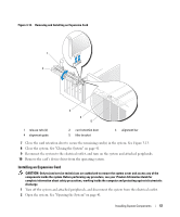
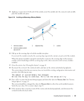
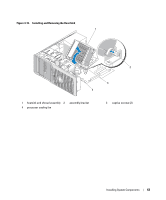
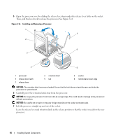
11 Open the system. See "Opening the System" on page 41. 12 Ensure that the installed memory modules are seated properly in their connectors, and repeat step 7 through step 9. 13 When the Memory Info value is correct, press to exit the System Setup program. 14 Run the system diagnostics to verify that the memory modules are operating properly. See "Running the System Diagnostics" on page 98. Microprocessor You can upgrade the system processor to take advantage of future options in speed and functionality. The processor and its associated internal cache memory are contained in a land grid array (LGA) package. Removing the Processor CAUTION: Only trained service technicians are authorized to remove the system cover and access any of the components inside the system. Before performing any procedure, see your Product Information Guide for complete information about safety precautions, working inside the computer and protecting against electrostatic discharge. CAUTION: The processor and heat sink can get very hot during normal operation. Ensure that they have had sufficient time to cool before you touch them. 1 Turn off the system and attached peripherals, and disconnect the system from the electrical outlet. 2 Open the system. See "Opening the System" on page 41. 3 Using a #2 Phillips screwdriver, loosen the two captive screws holding the heat sink and shroud assembly in place. These captive screws are adjacent to the processor cooling fan housing. See Figure 3-15. 4 Tilt the heat sink and shroud assembly away from the fan housing and lift it out. 62 Installing System Components
-
 1
1 -
2
-
3
-
4
-
5
-
6
-
7
-
8
-
9
-
10
-
11
-
12
-
13
-
14
-
15
-
16
-
17
-
18
-
19
-
20
-
21
-
22
-
23
-
24
-
25
-
26
-
27
-
28
-
29
-
30
-
31
-
32
-
33
-
34
-
35
-
36
-
37
-
38
-
39
-
40
-
41
-
42
-
43
-
44
-
45
-
46
-
47
-
48
-
49
-
50
-
51
-
52
-
53
-
54
-
55
-
56
-
 57
57 -
 58
58 -
 59
59 -
 60
60 -
 61
61 -
 62
62 -
 63
63 -
 64
64 -
 65
65 -
 66
66 -
 67
67 -
68
-
69
-
70
-
71
-
72
-
73
-
74
-
75
-
76
-
77
-
78
-
79
-
80
-
81
-
82
-
83
-
84
-
85
-
86
-
87
-
88
-
89
-
90
-
91
-
92
-
93
-
94
-
95
-
96
-
97
-
98
-
99
-
100
-
101
-
102
-
103
-
104
-
105
-
106
-
107
-
108
-
109
-
110
-
111
-
112
-
113
-
114
-
115
-
116
-
117
-
118
-
119
-
120
-
121
-
122
-
123
-
124
-
125
-
126
-
127
-
128
-
129
-
130
-
131
-
132
-
133
-
134
-
135
-
136
-
137
-
138
-
139
-
140
-
141
-
142
-
143
-
144
 |
 |
