Dell PowerEdge SC440 Hardware Owner's Manual - Page 56
Expansion Cards, Removing an Expansion Card
 |
View all Dell PowerEdge SC440 manuals
Add to My Manuals
Save this manual to your list of manuals |
Page 56 highlights
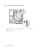
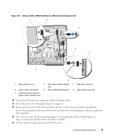
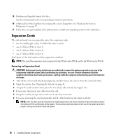
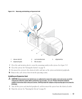
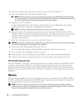
15 Partition and logically format the drive. See the documentation for your operating system for instructions. 16 (Optional) Test the hard drive by running the system diagnostics. See "Running the System Diagnostics" on page 97. 17 If the drive you just installed is the primary drive, install your operating system on the hard drive. Expansion Cards The system board can accommodate up to five expansion cards: • two 5-V, half-length 32-bit, 33-MHz PCI (slots 3 and 5) • one 2.5-Gb/sec PCIe x1 (slot 1) • one 2.5-Gb/sec PCIe x4 (slot 4) • one 2.5-Gb/sec PCIe x8 (slot 2) See Figure 6-2 for the location of the expansion card slots. NOTE: The size of the expansion card connectors for the PCI x4 card is PCIx 8, and for the PCI x8 card is PCI x16. Removing an Expansion Card CAUTION: Only trained service technicians are authorized to remove the system cover and access any of the components inside the system. Before performing any procedure, see your Product Information Guide for complete information about safety precautions, working inside the computer and protecting against electrostatic discharge. 1 Turn off the system and attached peripherals, and disconnect the system from the electrical outlet. 2 Open the system. See "Opening the System" on page 41. 3 To open the card retention door, press the two release tabs inward. See Figure 3-13. 4 If necessary, disconnect any cables from the card. 5 Grasp the card by its top corners and ease it out of its connector. 6 If you are removing the card permanently, install a filler bracket in the empty card slot. NOTE: Filler brackets must be installed over empty expansion card slots to maintain Federal Communications Commission (FCC) certification of the system. The brackets also keep dust and dirt out of the system and aid in proper cooling and airflow inside the system. 56 Installing System Components
-
 1
1 -
2
-
3
-
4
-
5
-
6
-
7
-
8
-
9
-
10
-
11
-
12
-
13
-
14
-
15
-
16
-
17
-
18
-
19
-
20
-
21
-
22
-
23
-
24
-
25
-
26
-
27
-
28
-
29
-
30
-
31
-
32
-
33
-
34
-
35
-
36
-
37
-
38
-
39
-
40
-
41
-
42
-
43
-
44
-
45
-
46
-
47
-
48
-
49
-
50
-
 51
51 -
 52
52 -
 53
53 -
 54
54 -
 55
55 -
 56
56 -
 57
57 -
 58
58 -
 59
59 -
 60
60 -
 61
61 -
62
-
63
-
64
-
65
-
66
-
67
-
68
-
69
-
70
-
71
-
72
-
73
-
74
-
75
-
76
-
77
-
78
-
79
-
80
-
81
-
82
-
83
-
84
-
85
-
86
-
87
-
88
-
89
-
90
-
91
-
92
-
93
-
94
-
95
-
96
-
97
-
98
-
99
-
100
-
101
-
102
-
103
-
104
-
105
-
106
-
107
-
108
-
109
-
110
-
111
-
112
-
113
-
114
-
115
-
116
-
117
-
118
-
119
-
120
-
121
-
122
-
123
-
124
-
125
-
126
-
127
-
128
-
129
-
130
-
131
-
132
-
133
-
134
-
135
-
136
-
137
-
138
-
139
-
140
-
141
-
142
-
143
-
144
 |
 |
