Dell PowerEdge SC440 Hardware Owner's Manual - Page 50
Close the system. See Closing the System on cooling vents.
 |
View all Dell PowerEdge SC440 manuals
Add to My Manuals
Save this manual to your list of manuals |
Page 50 highlights
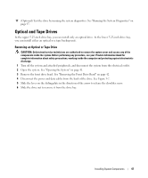
Figure 3-8. Installing Optical or Tape Drive Shoulder Screws 1 1 screws (3) 8 Gently slide the drive into place until you hear a click or feel the drive securely installed. 9 Attach the power cable to the drive. See Figure 3-7. 10 Attach the data cable: • If you are installing an IDE drive, another drive may be attached to the same data cable by another connector. Connect the data cable to the IDE connector on the system board. See Figure 3-7. • If you are installing a SCSI tape drive, connect the SCSI interface cable in the drive kit from the SCSI controller card to the drive. 11 Check all cable connections, and fold cables out of the way to allow for airflow between the fan and cooling vents. 12 Replace the front drive bezel. See "Replacing the Front Drive Bezel" on page 43. 13 Close the system. See "Closing the System" on page 41. 14 Reconnect the system to the electrical outlet, and turn on the system and attached peripherals. 15 If you installed an IDE drive, enter the System Setup program and ensure that the drive's IDE controller is enabled. See "Using the System Setup Program" on page 27. 16 (Optional) Test the drive by running the system diagnostics. See "Running the System Diagnostics" on page 97. 50 Installing System Components
-
 1
1 -
2
-
3
-
4
-
5
-
6
-
7
-
8
-
9
-
10
-
11
-
12
-
13
-
14
-
15
-
16
-
17
-
18
-
19
-
20
-
21
-
22
-
23
-
24
-
25
-
26
-
27
-
28
-
29
-
30
-
31
-
32
-
33
-
34
-
35
-
36
-
37
-
38
-
39
-
40
-
41
-
42
-
43
-
44
-
 45
45 -
 46
46 -
 47
47 -
 48
48 -
 49
49 -
 50
50 -
 51
51 -
 52
52 -
 53
53 -
 54
54 -
 55
55 -
56
-
57
-
58
-
59
-
60
-
61
-
62
-
63
-
64
-
65
-
66
-
67
-
68
-
69
-
70
-
71
-
72
-
73
-
74
-
75
-
76
-
77
-
78
-
79
-
80
-
81
-
82
-
83
-
84
-
85
-
86
-
87
-
88
-
89
-
90
-
91
-
92
-
93
-
94
-
95
-
96
-
97
-
98
-
99
-
100
-
101
-
102
-
103
-
104
-
105
-
106
-
107
-
108
-
109
-
110
-
111
-
112
-
113
-
114
-
115
-
116
-
117
-
118
-
119
-
120
-
121
-
122
-
123
-
124
-
125
-
126
-
127
-
128
-
129
-
130
-
131
-
132
-
133
-
134
-
135
-
136
-
137
-
138
-
139
-
140
-
141
-
142
-
143
-
144
 |
 |
