HP Cluster Platform Interconnects v2010 HP Cluster Platform InfiniBand Interco - Page 32
Externally Managed ISR 9024 Front Panel, 2.1.4 ISR 9024 Rear Panel
 |
View all HP Cluster Platform Interconnects v2010 manuals
Add to My Manuals
Save this manual to your list of manuals |
Page 32 highlights
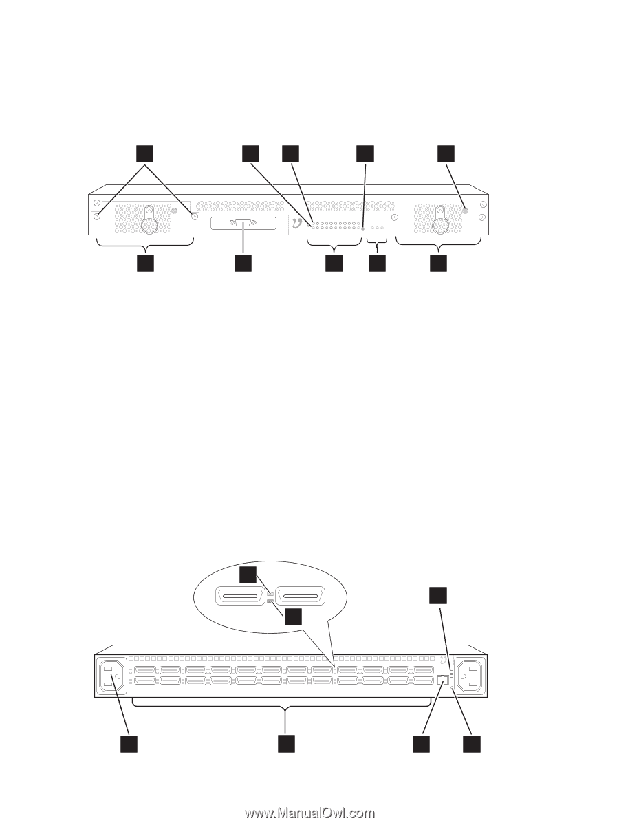
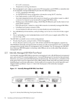
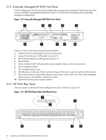
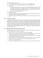
2.1.3 Externally Managed ISR 9024 Front Panel In this configuration, the I²C port panel replaces the management card panel. The I²C port provides access to channel management functions. Figure 2-3 shows the front panel of the externally managed configuration. Figure 2-3 Externally Managed ISR 9024, Front Panel 1 2 3 4 5 6 7 8 9 10 Figure 2-3 shows the following front panel features: 1. Captive fasteners retaining the power supply unit. 2. Logical link indicator LED (amber) for port 13. 3. Physical link indicator LED (green) for port 13. 4. Reset button. 5. Status indicator LED indicating the power supply status, and hot swap status. 6. Power supply module. 7. I2C communications port. 8. InfiniBand port indicator LEDs (amber for logical link status , green for physical link status. 9. Three interconnect status LEDs that show the status of the entire unit, the subnet manager (active, passive or standby), and power status. 10. Optional second power supply module. 2.1.4 ISR 9024 Rear Panel The rear panel is identical in both configurations and is shown in Figure 2-4. Figure 2-4 ISR 9024 Rear Panel (InfiniBand Ports) 1 4 2 5 6 32 Installing and Maintaining the ISR 9024 Interconnect 7 3
-
 1
1 -
2
-
3
-
4
-
5
-
6
-
7
-
8
-
9
-
10
-
11
-
12
-
13
-
14
-
15
-
16
-
17
-
18
-
19
-
20
-
21
-
22
-
23
-
24
-
25
-
26
-
 27
27 -
 28
28 -
 29
29 -
 30
30 -
 31
31 -
 32
32 -
 33
33 -
 34
34 -
 35
35 -
 36
36 -
 37
37 -
38
-
39
-
40
-
41
-
42
-
43
-
44
-
45
-
46
-
47
-
48
-
49
-
50
-
51
-
52
-
53
-
54
-
55
-
56
-
57
-
58
-
59
-
60
-
61
-
62
-
63
-
64
-
65
-
66
-
67
-
68
-
69
-
70
-
71
-
72
-
73
-
74
-
75
-
76
-
77
-
78
-
79
-
80
-
81
-
82
-
83
-
84
-
85
-
86
-
87
-
88
-
89
-
90
-
91
-
92
-
93
-
94
-
95
-
96
-
97
-
98
-
99
-
100
-
101
-
102
-
103
-
104
-
105
-
106
-
107
-
108
-
109
-
110
-
111
-
112
-
113
-
114
-
115
-
116
-
117
-
118
-
119
-
120
-
121
-
122
-
123
-
124
-
125
-
126
-
127
-
128
-
129
-
130
-
131
-
132
-
133
-
134
-
135
-
136
-
137
-
138
-
139
-
140
 |
 |