HP Cluster Platform Interconnects v2010 HP Cluster Platform InfiniBand Interco - Page 52
ISR ISR 9XXX Control Panels and Reset Buttons, 4.2 Unpacking the Chassis
 |
View all HP Cluster Platform Interconnects v2010 manuals
Add to My Manuals
Save this manual to your list of manuals |
Page 52 highlights
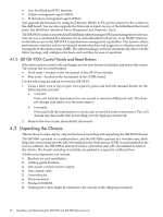
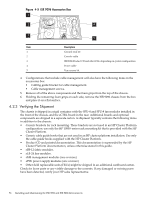
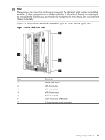
• Low level link and PHY function. • Subnet management agent (SMA). • Performance management agent (PMA). You upgrade the firmware by using the Ethernet, RS232, or I²C port to connect to the system on the sMB board. You can also upgrade the firmware in-band via any of the InfiniBand line board ports. See theVoltaire InfiniBand Fabric Management and Diagnostic Guide. The ISR 9XXX features an embedded InfiniBand subnet manager (SM) and management software. You can use a command line interface (CLI), and embedded web server, or an SNMP interface for flexible access to the ISR 9XXX comprehensive management capabilities. The system collects performance statistics and environmental monitoring data and supports an industry-standard management information base (MIB). The subnet manager software automatically discovers the fabric topology and configures the hosts and switches for ease of operation. 4.1.5 ISR ISR 9XXX Control Panels and Reset Buttons If the interconnect system locks up (hangs) use the reset button to initialize and restart the system. The system has two reset buttons: • Front reset - located on the front panel of the sFU-8 fan module. • Rear reset - located on the front panel of the sCTRL board. Use the following procedure to reset the ISR 9XXX: 1. Using a thick wire or tip of a pen (not a pencil), press and hold the recessed button for the following time periods: a. 1 second. Press and hold the reset button for one second to reset the sMB board only. This does not disrupt data traffic over the interconnect. b. 6 seconds. Press and hold the reset button for six seconds to reset the entire interconnect. This will disrupt any data traffic that is travelling over the high-speed network. 2. Remove the wire or pen immediately afterwards. 4.2 Unpacking the Chassis This section provides step-by-step instructions for packing and unpacking the ISR 9XXX chassis. The ISR 9096 is packed in a cardboard box, and the ISR 9288 is packed in a wooden crate. Both ship with a horizontal fan unit (sFU-8) installed in the front and an sCTRL board installed in the rear. In addition, the ISR 9288 is delivered with a vertical fan unit (sFU-4) installed in front of the chassis. The boards and plug-in modules are packed in a separate cardboard box. Additional components can include: 1. Brackets for rack installation. 2. Cabling guide brackets. 3. One power cord per power supply. 4. One console cable. 5. Grounding kit. 6. Documentation. 7. Product CD-ROM. 8. Packing list (which might be attached to the outside of the shipping container). 52 Installing and Maintaining the ISR 9096 and ISR 9288 Interconnects
-
 1
1 -
2
-
3
-
4
-
5
-
6
-
7
-
8
-
9
-
10
-
11
-
12
-
13
-
14
-
15
-
16
-
17
-
18
-
19
-
20
-
21
-
22
-
23
-
24
-
25
-
26
-
27
-
28
-
29
-
30
-
31
-
32
-
33
-
34
-
35
-
36
-
37
-
38
-
39
-
40
-
41
-
42
-
43
-
44
-
45
-
46
-
 47
47 -
 48
48 -
 49
49 -
 50
50 -
 51
51 -
 52
52 -
 53
53 -
 54
54 -
 55
55 -
 56
56 -
 57
57 -
58
-
59
-
60
-
61
-
62
-
63
-
64
-
65
-
66
-
67
-
68
-
69
-
70
-
71
-
72
-
73
-
74
-
75
-
76
-
77
-
78
-
79
-
80
-
81
-
82
-
83
-
84
-
85
-
86
-
87
-
88
-
89
-
90
-
91
-
92
-
93
-
94
-
95
-
96
-
97
-
98
-
99
-
100
-
101
-
102
-
103
-
104
-
105
-
106
-
107
-
108
-
109
-
110
-
111
-
112
-
113
-
114
-
115
-
116
-
117
-
118
-
119
-
120
-
121
-
122
-
123
-
124
-
125
-
126
-
127
-
128
-
129
-
130
-
131
-
132
-
133
-
134
-
135
-
136
-
137
-
138
-
139
-
140
 |
 |