HP Cluster Platform Interconnects v2010 HP Cluster Platform InfiniBand Interco - Page 62
Attaching the Cable Management Hooks,
 |
View all HP Cluster Platform Interconnects v2010 manuals
Add to My Manuals
Save this manual to your list of manuals |
Page 62 highlights
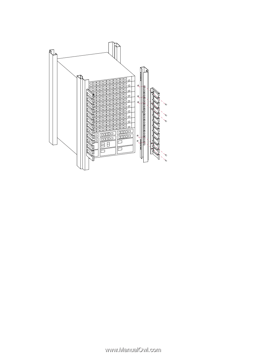
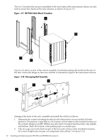
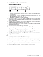
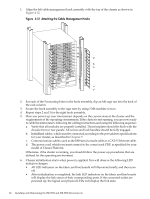
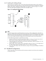
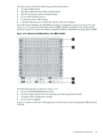
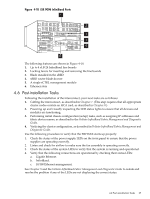
1. Align the left cable management hook assembly with the top of the chassis as shown in Figure 4-12. Figure 4-12 Attaching the Cable Management Hooks 2. For each of the 5 mounting holes in the hook assembly, clip an M6 cage nut into the back of the rack column. 3. Secure the hook assembly to the cage nuts by using 5 M6 machine screws. 4. Repeat steps 2 and 3 for the right hook assembly. 5. How you power up your interconnect depends on the current state of the cluster and the requirements of the operating environment. If the cluster is not running, you are now ready to cable the interconnect, following the cabling instructions and using the following sequence: a. Verify that all modules are properly installed. Their faceplates should be flush with the chassis front or rear panels. All screws and lock handles should be fully engaged. b. InfiniBand cables, which must be connected according to the port address specifications for your cluster, as described in Chapter 7. c. Communications cables, such as the DB9 serial console cable or a CAT-V Ethernet cable. d. The power cord, which you must connect to the correct rack PDU as specified for your model of Cluster Platform. Otherwise, if the cluster is running, you should follow the power-up procedures that are defined for the operating environment. 6. Chassis initialization starts when power is applied. You will observe the following LED indicator changes: • All LED indicators on the fabric and line boards will illuminate briefly, and then turn off. • After initialization is completed, the link LED indicators on the fabric and line boards will display the link status of their corresponding ports. If the connected nodes are powered up, the logical and physical LEDs will display the link state. 62 Installing and Maintaining the ISR 9096 and ISR 9288 Interconnects
-
 1
1 -
2
-
3
-
4
-
5
-
6
-
7
-
8
-
9
-
10
-
11
-
12
-
13
-
14
-
15
-
16
-
17
-
18
-
19
-
20
-
21
-
22
-
23
-
24
-
25
-
26
-
27
-
28
-
29
-
30
-
31
-
32
-
33
-
34
-
35
-
36
-
37
-
38
-
39
-
40
-
41
-
42
-
43
-
44
-
45
-
46
-
47
-
48
-
49
-
50
-
51
-
52
-
53
-
54
-
55
-
56
-
 57
57 -
 58
58 -
 59
59 -
 60
60 -
 61
61 -
 62
62 -
 63
63 -
 64
64 -
 65
65 -
 66
66 -
 67
67 -
68
-
69
-
70
-
71
-
72
-
73
-
74
-
75
-
76
-
77
-
78
-
79
-
80
-
81
-
82
-
83
-
84
-
85
-
86
-
87
-
88
-
89
-
90
-
91
-
92
-
93
-
94
-
95
-
96
-
97
-
98
-
99
-
100
-
101
-
102
-
103
-
104
-
105
-
106
-
107
-
108
-
109
-
110
-
111
-
112
-
113
-
114
-
115
-
116
-
117
-
118
-
119
-
120
-
121
-
122
-
123
-
124
-
125
-
126
-
127
-
128
-
129
-
130
-
131
-
132
-
133
-
134
-
135
-
136
-
137
-
138
-
139
-
140
 |
 |