HP Cluster Platform Interconnects v2010 HP Cluster Platform InfiniBand Interco - Page 79
Installing a Router Blade, FCR Blade Front Panel, Table 6-6 FCR Blade LEDs
 |
View all HP Cluster Platform Interconnects v2010 manuals
Add to My Manuals
Save this manual to your list of manuals |
Page 79 highlights
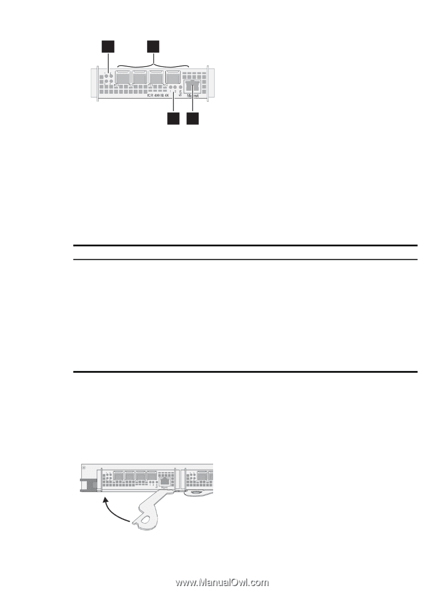
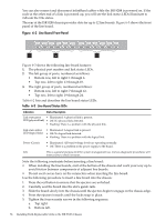
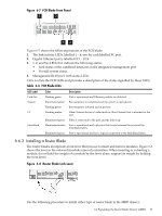
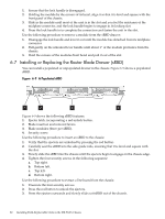
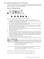
Figure 6-7 FCR Blade Front Panel 1 2 34 Figure 6-7 shows the following features of the FCR blade: 1. The link/activity LEDs, labelled 1 - 4, one for each labelled FC port. 2. Gigabit Ethernet ports, labelled FC1 - FC4. 3. 1, 2, and Sys LEDs that indicate the following status: • Link status of the combined interfaces in the integrated management port • Overall system status. 4. Management RJ-45 port, with status LEDs. Table 6-6 lists the FCR LEDs and provides a description of the status signalled by these LEDs. Table 6-6 FCR Blade LEDs LED Label Link/Act System FC InfiniBand Color Description Flashing green Port is operational and Ethernet packets are detected. Illuminated green Boot sequence is completed and the system is operational. Flashing green Boot sequence initiated and in process. Flashing amber Fibre Channel driver is loaded and no Fibre Channel link is attached to the port Illuminated green Fibre is connected to the port and the link is up. Illuminated amber Port is operational and a physical link exists between the port and the InfiniBand fabric. Illuminated green Port is operational and has a logical connection to the InfiniBand fabric. 6.6.3 Installing a Router Blade The router blades incorporate a lock lever that you use to insert and remove modules. Figure 6-8 shows the lever in the outward (module removal) orientation. When inserting or extracting a module, do not hold the weight of a module by the lever alone, support its weight by holding the front bezel. Figure 6-8 Router Blade Lock Lever Use the following procedure to install either type of router blade in the sRBD drawer: 6.6 Populating the Router Blade Drawer (sRBD) 79
-
 1
1 -
2
-
3
-
4
-
5
-
6
-
7
-
8
-
9
-
10
-
11
-
12
-
13
-
14
-
15
-
16
-
17
-
18
-
19
-
20
-
21
-
22
-
23
-
24
-
25
-
26
-
27
-
28
-
29
-
30
-
31
-
32
-
33
-
34
-
35
-
36
-
37
-
38
-
39
-
40
-
41
-
42
-
43
-
44
-
45
-
46
-
47
-
48
-
49
-
50
-
51
-
52
-
53
-
54
-
55
-
56
-
57
-
58
-
59
-
60
-
61
-
62
-
63
-
64
-
65
-
66
-
67
-
68
-
69
-
70
-
71
-
72
-
73
-
 74
74 -
 75
75 -
 76
76 -
 77
77 -
 78
78 -
 79
79 -
 80
80 -
 81
81 -
 82
82 -
 83
83 -
 84
84 -
85
-
86
-
87
-
88
-
89
-
90
-
91
-
92
-
93
-
94
-
95
-
96
-
97
-
98
-
99
-
100
-
101
-
102
-
103
-
104
-
105
-
106
-
107
-
108
-
109
-
110
-
111
-
112
-
113
-
114
-
115
-
116
-
117
-
118
-
119
-
120
-
121
-
122
-
123
-
124
-
125
-
126
-
127
-
128
-
129
-
130
-
131
-
132
-
133
-
134
-
135
-
136
-
137
-
138
-
139
-
140
 |
 |