HP Cluster Platform Interconnects v2010 HP Cluster Platform InfiniBand Interco - Page 81
Installing and Replacing the sCTRL Board, The temperature LED.
 |
View all HP Cluster Platform Interconnects v2010 manuals
Add to My Manuals
Save this manual to your list of manuals |
Page 81 highlights
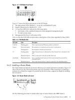
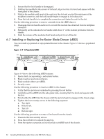
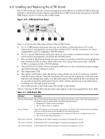
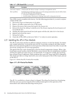
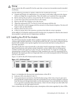
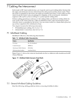
6.8 Installing and Replacing the sCTRL Board The sCTRL board provides the chassis management ports (Ethernet and RS-232 DB9 serial) and includes a reset button for the chassis. You install the sCTRL board on the rear panel of the ISR 9288 chassis. Figure 6-10 shows the sCTRL board. Figure 6-10 sCTRL Board Front Panel 1 2 3 4 56 7 Figure 6-10 shows the following features of the sCTRL board: 1. CLI-1, a DB9 format serial ports that you use to make a connection from a PC to the interconnect's management command-line interface (CLI). Use this connection for initial configuration, such as assigning a TCP/IP address. 2. CLI-2, a second DB9 format serial ports that you use to make a connection from a PC to the interconnect's management command-line interface (CLI). 3. Eth 1 and Eth 2 , Ethernet ports that you use to make a connection to the CLI or to its graphical user interface (GUI) via a Java client or Browser. You can use these ports only when the sCTRL is configured with a TCP/IP address, 4. SM and CM activity LEDs, which indicate the sMB card (1 or 2) on which the chassis manager and subnet manager software is active. 5. The temperature LED. 6. The chassis reset button. Push this button using a thick wire or tip of a pen (not a pencil) until the system reboots. Press the reset button for one second to perform a software reset that does not disrupt data traffic over the interconnect. Press and hold the reset button for six seconds to reset the entire interconnect, which will also disrupt any data traffic that is travelling over the high-speed network. 7. One of the security screws that secure the sCTRL to the chassis. Table 6-7 lists the sCTRL LEDs and provides a description of the status signalled by these LEDs. Table 6-7 sCTRL Board LEDs LED label Description sFB 1 to sFB 4 (Green) These LEDs indicate the presence of a fabric board in the chassis. Each LED corresponds to one fabric board slot and provides the following information: • Illuminated: A fabric board is installed. • Off: No fabric board is installed. Temp (Amber) These LEDs indicate an over-temperature fault on the chassis. This usually indicates a problem with one of the fan units and is signalled by the following states: • Illuminated: An over-temperature fault is detected. Check the cooling fan operation • Off: Normal operating temperature. SM Active 1 (Green) If illuminated, the subnet manager is running on management card #1 CM Active 1 (Green) If illuminated, the chassis manager is running on management card #1 SM Active 2 (Green) If illuminated, the subnet manager is running on management card #2 6.8 Installing and Replacing the sCTRL Board 81
-
 1
1 -
2
-
3
-
4
-
5
-
6
-
7
-
8
-
9
-
10
-
11
-
12
-
13
-
14
-
15
-
16
-
17
-
18
-
19
-
20
-
21
-
22
-
23
-
24
-
25
-
26
-
27
-
28
-
29
-
30
-
31
-
32
-
33
-
34
-
35
-
36
-
37
-
38
-
39
-
40
-
41
-
42
-
43
-
44
-
45
-
46
-
47
-
48
-
49
-
50
-
51
-
52
-
53
-
54
-
55
-
56
-
57
-
58
-
59
-
60
-
61
-
62
-
63
-
64
-
65
-
66
-
67
-
68
-
69
-
70
-
71
-
72
-
73
-
74
-
75
-
 76
76 -
 77
77 -
 78
78 -
 79
79 -
 80
80 -
 81
81 -
 82
82 -
 83
83 -
 84
84 -
 85
85 -
 86
86 -
87
-
88
-
89
-
90
-
91
-
92
-
93
-
94
-
95
-
96
-
97
-
98
-
99
-
100
-
101
-
102
-
103
-
104
-
105
-
106
-
107
-
108
-
109
-
110
-
111
-
112
-
113
-
114
-
115
-
116
-
117
-
118
-
119
-
120
-
121
-
122
-
123
-
124
-
125
-
126
-
127
-
128
-
129
-
130
-
131
-
132
-
133
-
134
-
135
-
136
-
137
-
138
-
139
-
140
 |
 |
