HP Cluster Platform Interconnects v2010 HP Cluster Platform InfiniBand Interco - Page 63
Installing the Cabling Clamps, 4.5 Standard Configurations
 |
View all HP Cluster Platform Interconnects v2010 manuals
Add to My Manuals
Save this manual to your list of manuals |
Page 63 highlights
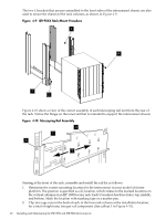
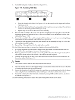
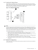
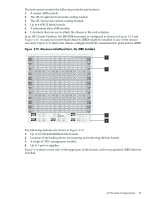
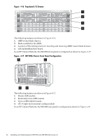
4.4.3 Installing the Cabling Clamps If line boards are installed in slots 1 and 2 of the chassis (the topmost slots) or the number of cables connected to the interconnect exceeds 128 and the interconnect is installed in a standard 600mm wide cabinet, additional cabling clamps are required, as shown in Figure 4-13, which shows the cable clamp installation on the rack's rear right column. Figure 4-13 Installing the Cabling Clamps 1 U23 2 U21 3 Note: The following procedure is optional and only necessary in older configurations when the two upper rows of the interconnect are used and when the cables connected to the interconnect exceed 128 and the interconnect is installed in a standard 600mm cabinet. A newer 800mm wide cabinet is now used in large InfiniBand configurations eliminating the need to use this procedure. Use the following procedure to install the four clamps: 1. Identify locations U21 and U23, identified by callout 1 in Figure 4-13 on the inner side of both rear rack columns. Mark these locations with a pen or masking tape. 2. Clip an M6 cage nut in the back of each location, indicated by callout 2 in Figure 4-13. Use a total of eight nuts, two per clamp. 3. Insert an M6 x 10mm machine screw, indicated by callout 2 in Figure 4-13, through each of the cable clamp's square mounting washers. Use two washers per clamp. 4. Secure the cable clamp to the rack columns by using a #2 cross-point (Phillips or Posidrive) screwdriver. 4.5 Standard Configurations Table 4-1 provides a list of modules and the maximum number of each that can be installed in an ISR 9XXX system. 4.5 Standard Configurations 63
-
 1
1 -
2
-
3
-
4
-
5
-
6
-
7
-
8
-
9
-
10
-
11
-
12
-
13
-
14
-
15
-
16
-
17
-
18
-
19
-
20
-
21
-
22
-
23
-
24
-
25
-
26
-
27
-
28
-
29
-
30
-
31
-
32
-
33
-
34
-
35
-
36
-
37
-
38
-
39
-
40
-
41
-
42
-
43
-
44
-
45
-
46
-
47
-
48
-
49
-
50
-
51
-
52
-
53
-
54
-
55
-
56
-
57
-
 58
58 -
 59
59 -
 60
60 -
 61
61 -
 62
62 -
 63
63 -
 64
64 -
 65
65 -
 66
66 -
 67
67 -
 68
68 -
69
-
70
-
71
-
72
-
73
-
74
-
75
-
76
-
77
-
78
-
79
-
80
-
81
-
82
-
83
-
84
-
85
-
86
-
87
-
88
-
89
-
90
-
91
-
92
-
93
-
94
-
95
-
96
-
97
-
98
-
99
-
100
-
101
-
102
-
103
-
104
-
105
-
106
-
107
-
108
-
109
-
110
-
111
-
112
-
113
-
114
-
115
-
116
-
117
-
118
-
119
-
120
-
121
-
122
-
123
-
124
-
125
-
126
-
127
-
128
-
129
-
130
-
131
-
132
-
133
-
134
-
135
-
136
-
137
-
138
-
139
-
140
 |
 |