HP Cluster Platform Interconnects v2010 HP Cluster Platform InfiniBand Interco - Page 36
Installing the ISR 9024 Power Supply Unit, 2.5 Operating the ISR 9024 Interconnect
 |
View all HP Cluster Platform Interconnects v2010 manuals
Add to My Manuals
Save this manual to your list of manuals |
Page 36 highlights
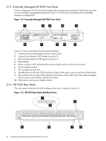
2.4 Installing the ISR 9024 Power Supply Unit An ISR 9024 contains either one or two power supplies in the side bays of the unit chassis, as shown in Figure 2-3. Warning: To maintain the correct cooling air flow, you must fill an unused power supply bay by using the supplied blank filler panel Use the following procedure to install or remove a power supply. You can do this when the interconnect is running 1. Unscrew the captive fasteners at each side of the filler panel and remove it from the front panel. Retain the filler panel for future use. 2. Position the rear (connector end) of the power supply in the empty bay. 3. Holding the power supply level with the chassis, slide it into the slot until it meets resistance at the chassis connector. Do not force the unit if you feel resistance, ensure that it is level and square with the bay. 4. Push the module further until it is completely seated on the connector, and its bezel is flush with the chassis front panel. 5. Use the captive fasteners at each side of the power supply to secure it in place. 2.5 Operating the ISR 9024 Interconnect To power up the interconnect and begin using it, use the following procedure: 1. Ensure that the following tasks are complete: a. The chassis is secured in the rack. b. Cabling is complete as described in Chapter 7. c. If not already connected, connect a power supply cable to the IEC inlets for each PSU installed (maximum two cables) to the adjacent power strip outlets located in the sides of the rack. d. All other cluster components are installed, cabled, and powered up. 2. Apply power to the interconnect, and verify the following LED status: a. The green power supply indicators at the front panel are illuminated. b. The green status LED on the front panel that is labelled SYS is illuminated. c. The green status LED on the front panel that is labelled SM is illuminated as follows: • Constant, for active mode. • Flashing, for standby mode. d. The green status LED on the front panel that is labelled PS is illuminated. 3. For each port that has a connected InfiniBand link cable: a. The green physical link LED is illuminated. b. The amber logical link LED is illuminated in one of the following states: • Constant, indicating the presence of a link with no data traffic passing over the link • Flashing, indicating the presence of a link with data traffic passing over the link. 2.6 Troubleshooting the ISR 9024 If any indicators are not illuminated as described in the preceding list, use the following verification procedure: 1. The PS LED does not illuminate. 2. The PSU is faulty. Replace the PSU. 36 Installing and Maintaining the ISR 9024 Interconnect
-
 1
1 -
2
-
3
-
4
-
5
-
6
-
7
-
8
-
9
-
10
-
11
-
12
-
13
-
14
-
15
-
16
-
17
-
18
-
19
-
20
-
21
-
22
-
23
-
24
-
25
-
26
-
27
-
28
-
29
-
30
-
 31
31 -
 32
32 -
 33
33 -
 34
34 -
 35
35 -
 36
36 -
 37
37 -
 38
38 -
 39
39 -
 40
40 -
 41
41 -
42
-
43
-
44
-
45
-
46
-
47
-
48
-
49
-
50
-
51
-
52
-
53
-
54
-
55
-
56
-
57
-
58
-
59
-
60
-
61
-
62
-
63
-
64
-
65
-
66
-
67
-
68
-
69
-
70
-
71
-
72
-
73
-
74
-
75
-
76
-
77
-
78
-
79
-
80
-
81
-
82
-
83
-
84
-
85
-
86
-
87
-
88
-
89
-
90
-
91
-
92
-
93
-
94
-
95
-
96
-
97
-
98
-
99
-
100
-
101
-
102
-
103
-
104
-
105
-
106
-
107
-
108
-
109
-
110
-
111
-
112
-
113
-
114
-
115
-
116
-
117
-
118
-
119
-
120
-
121
-
122
-
123
-
124
-
125
-
126
-
127
-
128
-
129
-
130
-
131
-
132
-
133
-
134
-
135
-
136
-
137
-
138
-
139
-
140
 |
 |