HP Cluster Platform Interconnects v2010 HP Cluster Platform InfiniBand Interco - Page 59
Resources Required to Perform an Installation, 4.4.2 Mounting The Chassis in the Rack, Warning
 |
View all HP Cluster Platform Interconnects v2010 manuals
Add to My Manuals
Save this manual to your list of manuals |
Page 59 highlights
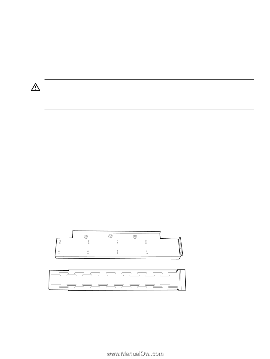
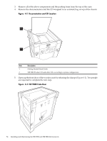
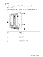
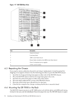
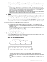
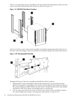
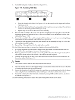
14U in the rack, and the ISR 9096 chassis occupies 6U in the rack. Under normal circumstances, the only reason for performing an installation is when you remove a complete chassis from its location in an existing HP Cluster Platform. Note the following constraints when replacing a chassis: • Ensure that the replacement of a chassis does not disrupt the proper ventilation, so that ambient temperature is maintained for air intake at the front of the chassis and exhaust at the chassis vents. All cable bundles must be routed according to the original design and cable route planning for your model of HP Cluster platform. • Ensure that you label the origin and destination of all cables, including power cables, Ethernet cables, and InfiniBand cables, if the cables are not already labelled. Warning! It is very important that you follow the original power distribution plan and connect the chassis power supplies to the correct distribution strips within the rack. This will ensure that the power draw is correctly distributed across the rack's redundant power distribution units. This section provides step-by-step instructions for installing the ISR 9XXX chassis. Two people are required to remove the interconnect from its box and mount it in a rack, due to its weight. 4.4.1 Resources Required to Perform an Installation The following materials and tools are required to mount the ISR 9XXX chassis into a rack: • Flat-blade screwdrivers of varying lengths and blade sizes, or an electric screwdriver with a selection of bits. • Cross-point (Posidrive or Phillips) screwdrivers of varying lengths and blade sizes, or an electric screwdriver with a selection of bits. • M6 cage nuts and a cage nut insertion tool. • 10mm x M6 machine screws. 4.4.2 Mounting The Chassis in the Rack You mount the ISR 9XXX interconnect with its ports facing the rear of the rack. The rail kit consist of two each of the components shown in Figure 4-8. Figure 4-8 ISR 9288 Interconnect Rail Kit • Two larger inner rails (top of Figure 4-8) provide a flange for the chassis to rest on. • Two smaller outer rails (bottom of Figure 4-8) attach to the larger rails to form a telescoping rail unit. • 16 machine screws (eight per pair of rails) are provided in the kit to secure the rails to each other. 4.4 Mounting the ISR 9XXX in the Rack 59
-
 1
1 -
2
-
3
-
4
-
5
-
6
-
7
-
8
-
9
-
10
-
11
-
12
-
13
-
14
-
15
-
16
-
17
-
18
-
19
-
20
-
21
-
22
-
23
-
24
-
25
-
26
-
27
-
28
-
29
-
30
-
31
-
32
-
33
-
34
-
35
-
36
-
37
-
38
-
39
-
40
-
41
-
42
-
43
-
44
-
45
-
46
-
47
-
48
-
49
-
50
-
51
-
52
-
53
-
 54
54 -
 55
55 -
 56
56 -
 57
57 -
 58
58 -
 59
59 -
 60
60 -
 61
61 -
 62
62 -
 63
63 -
 64
64 -
65
-
66
-
67
-
68
-
69
-
70
-
71
-
72
-
73
-
74
-
75
-
76
-
77
-
78
-
79
-
80
-
81
-
82
-
83
-
84
-
85
-
86
-
87
-
88
-
89
-
90
-
91
-
92
-
93
-
94
-
95
-
96
-
97
-
98
-
99
-
100
-
101
-
102
-
103
-
104
-
105
-
106
-
107
-
108
-
109
-
110
-
111
-
112
-
113
-
114
-
115
-
116
-
117
-
118
-
119
-
120
-
121
-
122
-
123
-
124
-
125
-
126
-
127
-
128
-
129
-
130
-
131
-
132
-
133
-
134
-
135
-
136
-
137
-
138
-
139
-
140
 |
 |