HP Cluster Platform Interconnects v2010 HP Cluster Platform InfiniBand Interco - Page 75
Installing or Replacing the sMB (Management) Board, The sMB Management Board
 |
View all HP Cluster Platform Interconnects v2010 manuals
Add to My Manuals
Save this manual to your list of manuals |
Page 75 highlights
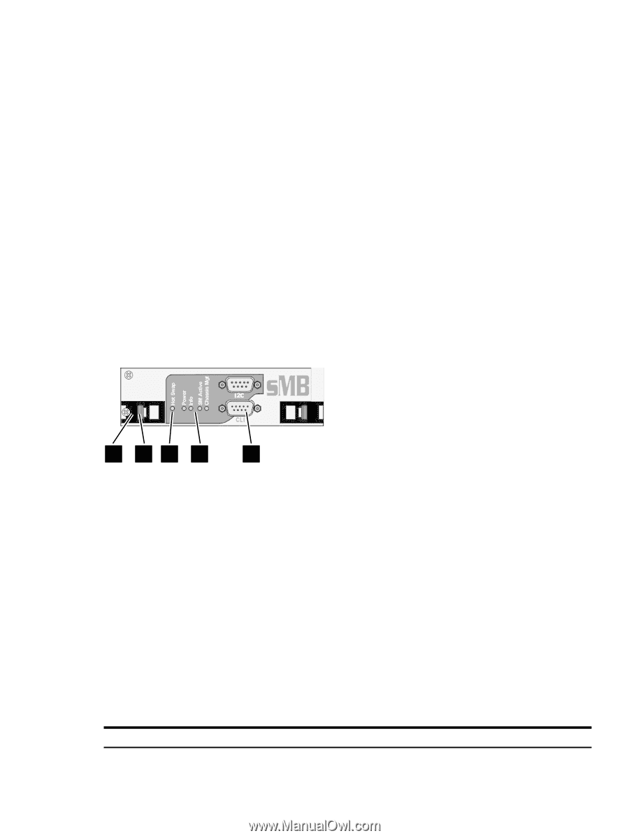
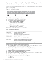
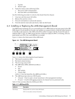
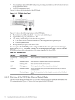
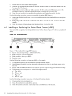
c. Top left. d. Bottom right. 6. Verify the status of the following LEDs: a. The power LED is illuminated. b. The info LED is not illuminated. Use the following procedure to extract a line board from the chassis: 1. Unsecure and disconnect all cables. 2. Release the security screws. 3. Press the red buttons to unlock the ejectors. 4. Press the ejectors outwards and slowly slide out the board. 6.4 Installing or Replacing the sMB (Management) Board An sMB board is optional, but you can install up to two sMB boards in the front panel of the ISR 9288 chassis. If you install two boards, one operate as a master (active), while the other board is in standby mode (passive). The sMB controls the subnet manager and the chassis through an adjacent sFB-12 card. An sMB cannot function without an adjacent sFB-12 is missing, and you must install one sFB-12 for each sMB that you install. Figure 6-4 shows the front panel of the sMB board. Figure 6-4 The sMB Management Board 1 23 4 5 Figure 6-3 shows the following line board features: 1. The board's top ejector latch. 2. Red latch release buttons. 3. The hot swap status LED. 4. The sMB status LEDs, labelled as follows: • Power • Info • SM Activity • Chassis Mgt. (Table 6-3 lists and describes the sMB board LEDs.) 5. The sMB board provides two RS232 ports: • CLI port - Used to make a local connection to the management interface. • I²C port - Used for debugging purposes, by trained service personnel only. Table 6-3 lists and describes the sMB board LEDs. Table 6-3 sMB Board LEDs Indication Hot Swap Description Illuminated: It is safe to extract the board. Off: It is not safe to extract the board. 6.4 Installing or Replacing the sMB (Management) Board 75
-
 1
1 -
2
-
3
-
4
-
5
-
6
-
7
-
8
-
9
-
10
-
11
-
12
-
13
-
14
-
15
-
16
-
17
-
18
-
19
-
20
-
21
-
22
-
23
-
24
-
25
-
26
-
27
-
28
-
29
-
30
-
31
-
32
-
33
-
34
-
35
-
36
-
37
-
38
-
39
-
40
-
41
-
42
-
43
-
44
-
45
-
46
-
47
-
48
-
49
-
50
-
51
-
52
-
53
-
54
-
55
-
56
-
57
-
58
-
59
-
60
-
61
-
62
-
63
-
64
-
65
-
66
-
67
-
68
-
69
-
 70
70 -
 71
71 -
 72
72 -
 73
73 -
 74
74 -
 75
75 -
 76
76 -
 77
77 -
 78
78 -
 79
79 -
 80
80 -
81
-
82
-
83
-
84
-
85
-
86
-
87
-
88
-
89
-
90
-
91
-
92
-
93
-
94
-
95
-
96
-
97
-
98
-
99
-
100
-
101
-
102
-
103
-
104
-
105
-
106
-
107
-
108
-
109
-
110
-
111
-
112
-
113
-
114
-
115
-
116
-
117
-
118
-
119
-
120
-
121
-
122
-
123
-
124
-
125
-
126
-
127
-
128
-
129
-
130
-
131
-
132
-
133
-
134
-
135
-
136
-
137
-
138
-
139
-
140
 |
 |