HP Cluster Platform Interconnects v2010 HP Cluster Platform InfiniBand Interco - Page 71
Installing Field-Replaceable Units in the ISR 9XXX Chassis, 6.1 Guidelines for Inserting
 |
View all HP Cluster Platform Interconnects v2010 manuals
Add to My Manuals
Save this manual to your list of manuals |
Page 71 highlights
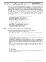
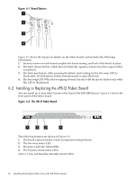
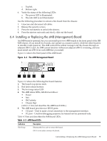
6 Installing Field-Replaceable Units in the ISR 9XXX Chassis The ISR 9288 chassis is pre-assembled with the fan units (sFU-4 and sFU-8) and the rear panel sCTRL board. You must install all boards in their designated slot to enable their full functionality. All boards are hot swap enabled (for some boards, only when the hot swap indicator LED is illuminated) and you can insert and extract these boards without turning off electrical power. Additional boards and modules might be shipped according to the system configuration and are assembled during installation. Alternatively, you might be swapping out a chassis only, and repopulating the new chassis with modules from and existing, defective, chassis. Every slot that is not populated with a module must be covered with a filler panel for proper cooling. The following FRU components are described: • Guidelines for inserting and extracting boards (Section 6.1). • Installing the sFB-12 fabric board (Section 6.2). • Installing the sLB-24 line board (Section 6.3). • Installing the sMB (management) board (Section 6.4). • Installing power supply units (Section 6.5). • Populating the sRBD router blade drawer (Section 6.6). • Installing the sRBD router blade drawer (Section 6.7). • Installing the sCTRL controller board ( Section 6.8). • Installing the sFU-4 fan unit (Section 6.9). • Installing the sFU-8 fan unit (Section 6.10). 6.1 Guidelines for Inserting and Extracting Boards Observe the following precautions when inserting and extracting boards. • Wear grounding wrist straps to avoid ESD damage. • To avoid risk of electric shock, do not touch the backplane with your hand or any metal tool. • Line, sFB-12, sMB, and other ISR 9288 boards have a pair of ejectors that lock the board in place and serve as a lever for seating or extracting. The ejectors snap inward to lock the board into place. • Before starting to extract a board, press the red button to disengage the lock. This button signals the extraction request to the interconnect. • Each ejector has a guide pin that slides into a groove in the chassis. If the guide pin is not perfectly aligned with this groove, you might experience difficulty in locking the ejector handles in place. Should this occur, manipulate the ejector handle gently until it locks into place • Insert screws manually at first to ensure that the screw engages directly on the thread and does not cross-thread. Tighten the screws with a screwdriver in the following sequence: 1. Top right. 2. Bottom left. 3. Top left. 4. Bottom right. • If you use a powered screwdriver, do not use a higher torque setting than 3. Settings higher than 3 might damage the screws. 6.1 Guidelines for Inserting and Extracting Boards 71
-
 1
1 -
2
-
3
-
4
-
5
-
6
-
7
-
8
-
9
-
10
-
11
-
12
-
13
-
14
-
15
-
16
-
17
-
18
-
19
-
20
-
21
-
22
-
23
-
24
-
25
-
26
-
27
-
28
-
29
-
30
-
31
-
32
-
33
-
34
-
35
-
36
-
37
-
38
-
39
-
40
-
41
-
42
-
43
-
44
-
45
-
46
-
47
-
48
-
49
-
50
-
51
-
52
-
53
-
54
-
55
-
56
-
57
-
58
-
59
-
60
-
61
-
62
-
63
-
64
-
65
-
 66
66 -
 67
67 -
 68
68 -
 69
69 -
 70
70 -
 71
71 -
 72
72 -
 73
73 -
 74
74 -
 75
75 -
 76
76 -
77
-
78
-
79
-
80
-
81
-
82
-
83
-
84
-
85
-
86
-
87
-
88
-
89
-
90
-
91
-
92
-
93
-
94
-
95
-
96
-
97
-
98
-
99
-
100
-
101
-
102
-
103
-
104
-
105
-
106
-
107
-
108
-
109
-
110
-
111
-
112
-
113
-
114
-
115
-
116
-
117
-
118
-
119
-
120
-
121
-
122
-
123
-
124
-
125
-
126
-
127
-
128
-
129
-
130
-
131
-
132
-
133
-
134
-
135
-
136
-
137
-
138
-
139
-
140
 |
 |