HP Cluster Platform Interconnects v2010 HP Cluster Platform InfiniBand Interco - Page 83
Installing the sFU-8 Fan Module
 |
View all HP Cluster Platform Interconnects v2010 manuals
Add to My Manuals
Save this manual to your list of manuals |
Page 83 highlights
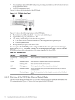
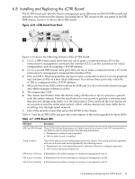
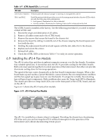
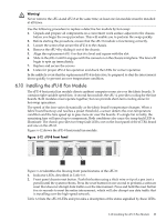
Warning! Never remove the sFU-4 and sFU-8 at the same time; at least one fan module must be installed at all times. Use the following procedure to replace a defective fan module by hot-swap: 1. Unpack and prepare all components on a convenient work surface adjacent to the chassis before you begin the swap procedure. This will enable you to preform the swap quickly. 2. Before starting the procedure, ensure that the sFU-8 module is functioning correctly. 3. Loosen the screws that secure the sFU-4 to the chassis. 4. Remove the sFU-4 by sliding it out of the chassis. 5. Align the replacement sFU-4 so that it is level and square with the slot. 6. Slide in the sFU-4 until it engages with the connector on the chassis mid-plane. The fans will begin to spin up immediately. 7. Replace and secure the screws. 8. Listen for proper sFU-4 fan operation and check the LEDs for correct operation In the unlikely event that the replacement sFU-4 is defective, be prepared to shut the interconnect down quickly to prevent an over-temperature condition. 6.10 Installing the sFU-8 Fan Module The sFU-8 horizontal fan module directs ambient computer room air over the fabric boards. It contains eight variable speed fans. A second fan module, the sFU-4, provides cooling for the line boards. Both modules must operate together, but can provide short-term cooling alone for hot-swap operations. The speed of the fans varies dynamically as the fabric board's temperature changes. When a fabric board heats up and reaches a preset threshold, a sensor detects the over-temperature condition and the fans speed up to pass more air over the boards. If a single fan is faulty, the remaining fans will speed up to compensate. Both conditions also cause the temp fault LED to illuminate. The chassis provides two temp fault LEDs; one on the front panel of the sCTRL board and one on the sFU-8. Figure 6-12 shows the sFU-8 horizontal fan module. Figure 6-12 sFU-8 Front Panel 1 2 Figure 6-12 identifies the flowing front panel features of the sFU-8: 1. Indicator LEDs, described in Table 6-8. 2. Front panel chassis reset button. Push this button using a thick wire or tip of a pen (not a pencil) until the system reboots. Press the reset button for one second to perform a software reset that does not disrupt data traffic over the interconnect. Press and hold the reset button for six seconds to reset the entire interconnect, which will also disrupt any data traffic that is travelling over the high-speed network. Table 6-8 lists the sFU-8 LEDs and provides a description of the status signalled by these LEDs. 6.10 Installing the sFU-8 Fan Module 83
-
 1
1 -
2
-
3
-
4
-
5
-
6
-
7
-
8
-
9
-
10
-
11
-
12
-
13
-
14
-
15
-
16
-
17
-
18
-
19
-
20
-
21
-
22
-
23
-
24
-
25
-
26
-
27
-
28
-
29
-
30
-
31
-
32
-
33
-
34
-
35
-
36
-
37
-
38
-
39
-
40
-
41
-
42
-
43
-
44
-
45
-
46
-
47
-
48
-
49
-
50
-
51
-
52
-
53
-
54
-
55
-
56
-
57
-
58
-
59
-
60
-
61
-
62
-
63
-
64
-
65
-
66
-
67
-
68
-
69
-
70
-
71
-
72
-
73
-
74
-
75
-
76
-
77
-
 78
78 -
 79
79 -
 80
80 -
 81
81 -
 82
82 -
 83
83 -
 84
84 -
 85
85 -
 86
86 -
 87
87 -
 88
88 -
89
-
90
-
91
-
92
-
93
-
94
-
95
-
96
-
97
-
98
-
99
-
100
-
101
-
102
-
103
-
104
-
105
-
106
-
107
-
108
-
109
-
110
-
111
-
112
-
113
-
114
-
115
-
116
-
117
-
118
-
119
-
120
-
121
-
122
-
123
-
124
-
125
-
126
-
127
-
128
-
129
-
130
-
131
-
132
-
133
-
134
-
135
-
136
-
137
-
138
-
139
-
140
 |
 |