HP Cluster Platform Interconnects v2010 HP Cluster Platform InfiniBand Interco - Page 60
ISR 9XXX Rack Mount Procedure, Telescoping Rail Assembly
 |
View all HP Cluster Platform Interconnects v2010 manuals
Add to My Manuals
Save this manual to your list of manuals |
Page 60 highlights
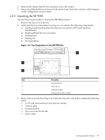
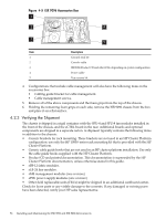
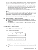
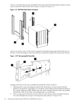
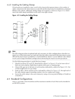
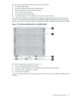
The two L-brackets that are pre-assembled to the front sides of the interconnect chassis are also used to secure the chassis to the rack columns, as shown in Figure 4-9. Figure 4-9 ISR 9XXX Rack Mount Procedure 3 4 1 2 Figure 4-10 shows a view of the correct assembly of each telescoping rail unit from the rear of the rack. Notice the flange on the inner rail that is intended to support the interconnect chassis Figure 4-10 Telescoping Rail Assembly 4 1 3 2 Starting at the front of the rack, assemble and install the rail kit as follows: 1. Determine the correct mounting location for the interconnect in your model of cluster platform. The position is specified as a U-location, which relates to the marked locations on the vertical columns of an HP 10000-series rack. Each U-location has three holes; top, middle, and bottom. Mark the location with masking tape or a marker pen. 2. Clip two cage nuts in the back of each of the four rack column at the installation location, for a total of eight nuts, two per rail component. (See callout 1 in Figure 4-10). 60 Installing and Maintaining the ISR 9096 and ISR 9288 Interconnects
-
 1
1 -
2
-
3
-
4
-
5
-
6
-
7
-
8
-
9
-
10
-
11
-
12
-
13
-
14
-
15
-
16
-
17
-
18
-
19
-
20
-
21
-
22
-
23
-
24
-
25
-
26
-
27
-
28
-
29
-
30
-
31
-
32
-
33
-
34
-
35
-
36
-
37
-
38
-
39
-
40
-
41
-
42
-
43
-
44
-
45
-
46
-
47
-
48
-
49
-
50
-
51
-
52
-
53
-
54
-
 55
55 -
 56
56 -
 57
57 -
 58
58 -
 59
59 -
 60
60 -
 61
61 -
 62
62 -
 63
63 -
 64
64 -
 65
65 -
66
-
67
-
68
-
69
-
70
-
71
-
72
-
73
-
74
-
75
-
76
-
77
-
78
-
79
-
80
-
81
-
82
-
83
-
84
-
85
-
86
-
87
-
88
-
89
-
90
-
91
-
92
-
93
-
94
-
95
-
96
-
97
-
98
-
99
-
100
-
101
-
102
-
103
-
104
-
105
-
106
-
107
-
108
-
109
-
110
-
111
-
112
-
113
-
114
-
115
-
116
-
117
-
118
-
119
-
120
-
121
-
122
-
123
-
124
-
125
-
126
-
127
-
128
-
129
-
130
-
131
-
132
-
133
-
134
-
135
-
136
-
137
-
138
-
139
-
140
 |
 |
