HP Cluster Platform Interconnects v2010 HP Cluster Platform InfiniBand Interco - Page 42
ISR 9024 S/D Rear Panel, Externally Managed ISR 9024 S/D, Front Panel
 |
View all HP Cluster Platform Interconnects v2010 manuals
Add to My Manuals
Save this manual to your list of manuals |
Page 42 highlights
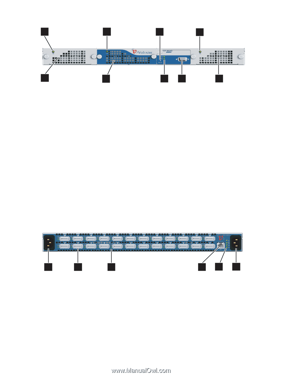
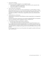
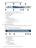
Figure 3-2 Externally Managed ISR 9024 S/D, Front Panel 1 3 5 8 2 4 67 9 Figure 2-3 shows the following front panel features: The following list corresponds to the callouts shown in Figure 3-2. 1. Power supply indicator. 2. Power supply module. 3. Fan unit indicator. 4. Fan unit. 5. Reset button. 6. System status LEDs include: • Info-User defined (for future use). • Pwr-System power status. 7. I²C Connector. Provides serial I²C interface. 8. Power supply indicator. 9. Power supply module. 3.1.3 ISR 9024 S/D Rear Panel The rear panel is identical in all ISR 9024 S/D RoHS compliant configurations and is shown in Figure 3-3. Figure 3-3 ISR 9024 S/D Rear Panel (InfiniBand Ports) 1 2 3 456 The following list corresponds to the callouts shown in Figure 3-3: 1. IEC power receptacle. 2. 24 4x InfiniBand ports. 3. Port LEDs include: • Logical Link (Amber) • Physical Link (Green) 4. Ethernet port. 5. System status LEDs include: • Subnet manager LED • Power Supply/Fan status LED 42 Installing and Maintaining the ISR 9024 S/D Interconnect (RoHS Compliant)
-
 1
1 -
2
-
3
-
4
-
5
-
6
-
7
-
8
-
9
-
10
-
11
-
12
-
13
-
14
-
15
-
16
-
17
-
18
-
19
-
20
-
21
-
22
-
23
-
24
-
25
-
26
-
27
-
28
-
29
-
30
-
31
-
32
-
33
-
34
-
35
-
36
-
 37
37 -
 38
38 -
 39
39 -
 40
40 -
 41
41 -
 42
42 -
 43
43 -
 44
44 -
 45
45 -
 46
46 -
 47
47 -
48
-
49
-
50
-
51
-
52
-
53
-
54
-
55
-
56
-
57
-
58
-
59
-
60
-
61
-
62
-
63
-
64
-
65
-
66
-
67
-
68
-
69
-
70
-
71
-
72
-
73
-
74
-
75
-
76
-
77
-
78
-
79
-
80
-
81
-
82
-
83
-
84
-
85
-
86
-
87
-
88
-
89
-
90
-
91
-
92
-
93
-
94
-
95
-
96
-
97
-
98
-
99
-
100
-
101
-
102
-
103
-
104
-
105
-
106
-
107
-
108
-
109
-
110
-
111
-
112
-
113
-
114
-
115
-
116
-
117
-
118
-
119
-
120
-
121
-
122
-
123
-
124
-
125
-
126
-
127
-
128
-
129
-
130
-
131
-
132
-
133
-
134
-
135
-
136
-
137
-
138
-
139
-
140
 |
 |