HP Cluster Platform Interconnects v2010 HP Cluster Platform InfiniBand Interco - Page 74
Line Board Front Panel, Table 6-2 Line Board Status LEDs
 |
View all HP Cluster Platform Interconnects v2010 manuals
Add to My Manuals
Save this manual to your list of manuals |
Page 74 highlights
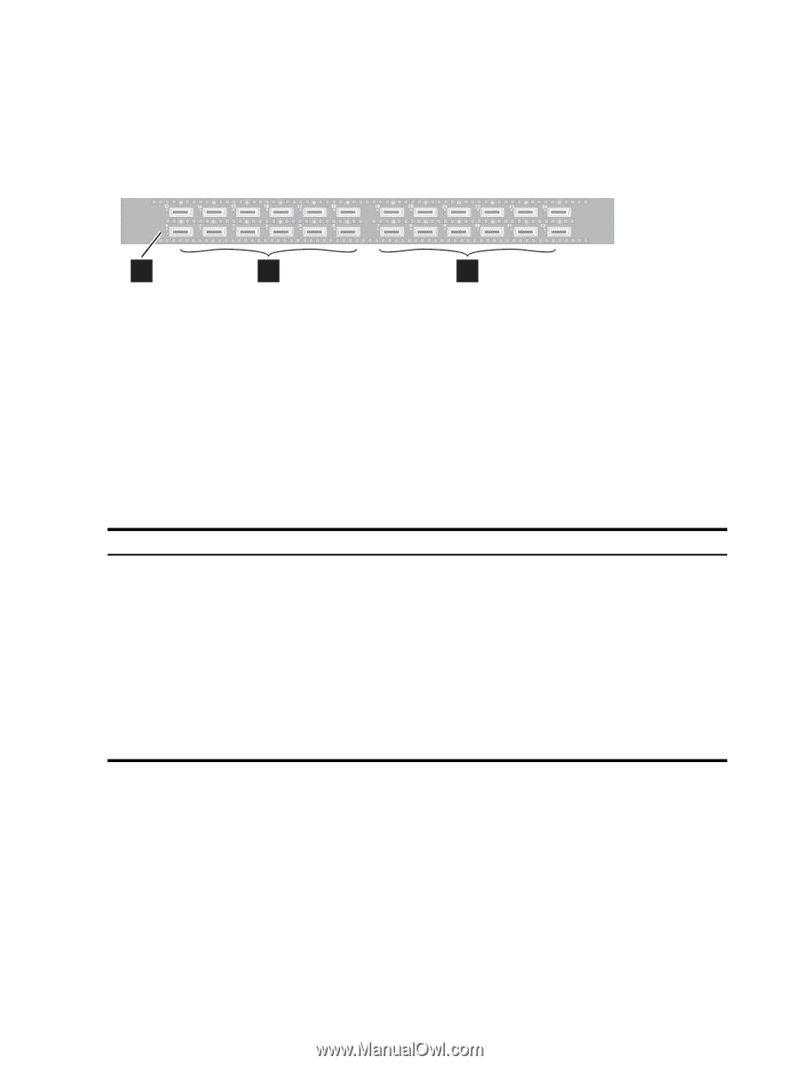
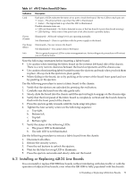
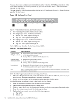
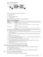
You can also connect and disconnect InfiniBand cables while the ISR 9288 is powered on. If the node at the other end of a link is powered up, you will see the link status LEDs illuminate to indicate the link status. The rear of the ISR 9288 chassis provides slots for up to 12 line boards. Figure 6-3 shows the front panel of the line board. Figure 6-3 Line Board Front Panel 1 2 3 Figure 6-3 shows the following line board features: 1. The physical port number and link status LEDs. 2. The left group of ports, numbered as follows: • Bottom row, left to right: 1 through 6. • Top row, left to right: 13 through 18. 3. The right group of ports, numbered as follows: • Bottom row, left to right: 7 through 12. • Top row, left to right: 19 through 24. Table 6-2 lists and describes the line board status LEDs. Table 6-2 Line Board Status LEDs Indication Status Description Link state green • Illuminated: A physical link is present. LED (physical link) • Off: No physical link detected. • Flashing: There is a problem with the physical link. Link state amber LED (logical link) • Illuminated: A logical link is present • Off: No logical link detected. • Flashing: There is a problem with the logical link. Power (Green) • Illuminated: All board voltage levels are operating normally. • Off: There is a problem in the power supply to the board. Info This is a general purpose LED for system management use. Various diagnostic procedures will instruct you to check its status. Note the following constraints before inserting a line board: • When installing the line boards, start at the bottom of the chassis and work your way up to avoid friction between components of adjacent line boards. • Do not exert excess force on the connectors when inserting the line board. Use the following procedure to insert a line board into the chassis: 1. Press the red button to ensure that the ejectors are unlocked. 2. Carefully seat the board into the slot's guide rails. 3. Slide the board slowly into the chassis until the ejectors begin to engage on the chassis edge. 4. Press the ejectors inwards until the locks snap in place. 5. Tighten the four security screws in the following sequence: a. Top right. b. Bottom left. 74 Installing Field-Replaceable Units in the ISR 9XXX Chassis
-
 1
1 -
2
-
3
-
4
-
5
-
6
-
7
-
8
-
9
-
10
-
11
-
12
-
13
-
14
-
15
-
16
-
17
-
18
-
19
-
20
-
21
-
22
-
23
-
24
-
25
-
26
-
27
-
28
-
29
-
30
-
31
-
32
-
33
-
34
-
35
-
36
-
37
-
38
-
39
-
40
-
41
-
42
-
43
-
44
-
45
-
46
-
47
-
48
-
49
-
50
-
51
-
52
-
53
-
54
-
55
-
56
-
57
-
58
-
59
-
60
-
61
-
62
-
63
-
64
-
65
-
66
-
67
-
68
-
 69
69 -
 70
70 -
 71
71 -
 72
72 -
 73
73 -
 74
74 -
 75
75 -
 76
76 -
 77
77 -
 78
78 -
 79
79 -
80
-
81
-
82
-
83
-
84
-
85
-
86
-
87
-
88
-
89
-
90
-
91
-
92
-
93
-
94
-
95
-
96
-
97
-
98
-
99
-
100
-
101
-
102
-
103
-
104
-
105
-
106
-
107
-
108
-
109
-
110
-
111
-
112
-
113
-
114
-
115
-
116
-
117
-
118
-
119
-
120
-
121
-
122
-
123
-
124
-
125
-
126
-
127
-
128
-
129
-
130
-
131
-
132
-
133
-
134
-
135
-
136
-
137
-
138
-
139
-
140
 |
 |