HP Cluster Platform Interconnects v2010 HP Cluster Platform InfiniBand Interco - Page 35
Voltaire InfiniBand Fabric, Management and Diagnostic Guide
 |
View all HP Cluster Platform Interconnects v2010 manuals
Add to My Manuals
Save this manual to your list of manuals |
Page 35 highlights
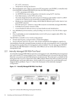
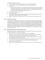
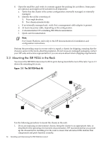
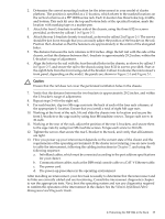
2. Determine the correct mounting location for the interconnect in your model of cluster platform. The position is specified as a U-location, which relates to the marked locations on the vertical columns an a HP 10000-series rack. Each U-location has three holes; top, middle, and bottom. This rack kit uses the top and bottom hole of the specified location. mark the location with masking tape or a marker pen. 3. Attach the front L-brackets to either side of the chassis, using the three 8/32-in screws provided, as shown by callout 1 in Figure 2-5. 4. Attach the rear L-brackets loosely to each rail, as shown by callout 2 in Figure 2-5. The screws should be just loose enough that you can easily adjust the position of the bracket on the rail. Position the L-bracket so that the fasteners are approximately in the centre of the elongated holes. 5. The distance between the rack columns is 29.2 inches. Align the left rail with the side of the chassis, so that the distance between the L-brackets is approximately 29.2 inches, within the L-bracket's range of adjustment. 6. Align the holes in the rail with the four threaded holes in the chassis, as shown by callout 3 in Figure 2-5, and secure the rail to the chassis using four 8/32-in screws provided. Start at the eighth hole from the front-facing end of the bracket. Callout 4 indicates the interconnect's front panel, depending on the model, the panels are shown in Figure 2-3 and Figure 2-1. Caution: Ensure that the rail does not cover the perforated ventilation holes in the chassis. 7. Verify that the distance between the two brackets is approximately 29.2 inches, and within the L-bracket's range of adjustment. 8. Repeat steps 2-4 for the right rail. 9. For each bracket, clip two M6 cage nuts into the back of each of the four rack columns, at the appropriate U-location. Ensure that you install a total of eight M6 cage nuts. 10. Working at the front of the rack, lift and slide the chassis into its location and secure the front L-brackets to the cage nuts by using four M6 machine screws. Torque each screw to 30-in/lb. 11. Working at the rear of the rack, adjust the position of the rear L-brackets, and secure them to the cage nuts by using four M6 machine screws. Torque each screw to 30-in/lb. 12. Tighten the screws that secure the rear L-bracket to the track, and verify that all fasteners are tight. 13. How you power up your interconnect depends on the current state of the cluster and the requirements of the operating environment. If the cluster is not running, you are now ready to cable the interconnect, following the cabling instructions in Chapter 7, and using the following sequence: a. InfiniBand cables, which must be connected according to the port address specifications for your cluster. b. Communications cables, such as the DB9 serial console cable or a CAT-V Ethernet cable. c. The power cord. d. The power-up procedures in the operating environment. After installing an interconnect, your first task is usually to determine that the interconnect and its links are correctly cabled and are functioning. Consult the interconnect diagnostics chapter to run the appropriate tests. Next, boot the operating system and run any diagnostics required to confirm the operation of the interconnect in the cluster. See the Voltaire InfiniBand Fabric Management and Diagnostic Guide . 2.3 Mounting the ISR 9024 in the Rack 35
-
 1
1 -
2
-
3
-
4
-
5
-
6
-
7
-
8
-
9
-
10
-
11
-
12
-
13
-
14
-
15
-
16
-
17
-
18
-
19
-
20
-
21
-
22
-
23
-
24
-
25
-
26
-
27
-
28
-
29
-
 30
30 -
 31
31 -
 32
32 -
 33
33 -
 34
34 -
 35
35 -
 36
36 -
 37
37 -
 38
38 -
 39
39 -
 40
40 -
41
-
42
-
43
-
44
-
45
-
46
-
47
-
48
-
49
-
50
-
51
-
52
-
53
-
54
-
55
-
56
-
57
-
58
-
59
-
60
-
61
-
62
-
63
-
64
-
65
-
66
-
67
-
68
-
69
-
70
-
71
-
72
-
73
-
74
-
75
-
76
-
77
-
78
-
79
-
80
-
81
-
82
-
83
-
84
-
85
-
86
-
87
-
88
-
89
-
90
-
91
-
92
-
93
-
94
-
95
-
96
-
97
-
98
-
99
-
100
-
101
-
102
-
103
-
104
-
105
-
106
-
107
-
108
-
109
-
110
-
111
-
112
-
113
-
114
-
115
-
116
-
117
-
118
-
119
-
120
-
121
-
122
-
123
-
124
-
125
-
126
-
127
-
128
-
129
-
130
-
131
-
132
-
133
-
134
-
135
-
136
-
137
-
138
-
139
-
140
 |
 |