HP Cluster Platform Interconnects v2010 HP Cluster Platform InfiniBand Interco - Page 77
Populating the Router Blade Drawer (sRBD), 6.6.1 Overview of the IPR (TCP/IP) Blade
 |
View all HP Cluster Platform Interconnects v2010 manuals
Add to My Manuals
Save this manual to your list of manuals |
Page 77 highlights
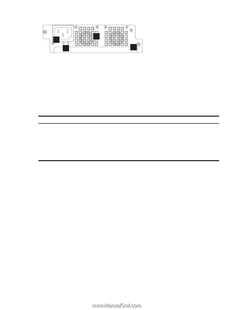
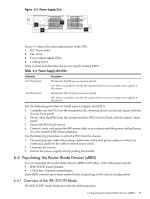
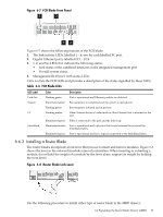
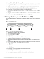
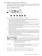
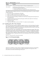
Figure 6-5 Power Supply Unit 2 1 3 4 Figure 6-5 shows the following features of the PSU: 1. IEC Power Inlet. 2. Fan vents. 3. Power status signal LEDs. 4. Locking screw. Table 6-4 lists and describes the power supply module LEDs. Table 6-4 Power Supply Unit LEDs Indication DC ON (Green) AC ON (Green) Description Illuminated: The DC power source is present. Off: There is a problem with the DC supply. Otherwise, power might not be applied to the chassis. Illuminated: The AC power source is present. Off: There is a problem with the AC supply. Otherwise, power might not be applied to the chassis. Use the following procedure to install a power supply unit (PSU): 1. Carefully seat the PSU into the designated slot, ensuring that it is level and square with the chassis' front panel. 2. Slowly slide the (PSU) into the chassis until the PSU's bezel is flush with the chassis' front panel. 3. Secure the PSU bezel screws. 4. Connect, route, and secure the 48V power cable in accordance with the power cabling layout for your model of HP cluster platform. Use the following procedure to extract a PSU from the chassis: 1. Disconnect power cable after taking careful note of the rack power outlet to which it is connected, and how the cable is routed and secured. 2. Unsecure the screws. 3. Extract the power supply unit by pulling the handle. 6.6 Populating the Router Blade Drawer (sRBD) You can populate the router blade drawer (sRBD) with either of the following modules: • IPR (TCP/IP router) blades. • FCR (Fibre Channel router) blades. Each sRBD contains up to three router blades, depending on the chassis configuration. 6.6.1 Overview of the IPR (TCP/IP) Blade The IPR TCP/IP router blade provides the following ports: 6.6 Populating the Router Blade Drawer (sRBD) 77
-
 1
1 -
2
-
3
-
4
-
5
-
6
-
7
-
8
-
9
-
10
-
11
-
12
-
13
-
14
-
15
-
16
-
17
-
18
-
19
-
20
-
21
-
22
-
23
-
24
-
25
-
26
-
27
-
28
-
29
-
30
-
31
-
32
-
33
-
34
-
35
-
36
-
37
-
38
-
39
-
40
-
41
-
42
-
43
-
44
-
45
-
46
-
47
-
48
-
49
-
50
-
51
-
52
-
53
-
54
-
55
-
56
-
57
-
58
-
59
-
60
-
61
-
62
-
63
-
64
-
65
-
66
-
67
-
68
-
69
-
70
-
71
-
 72
72 -
 73
73 -
 74
74 -
 75
75 -
 76
76 -
 77
77 -
 78
78 -
 79
79 -
 80
80 -
 81
81 -
 82
82 -
83
-
84
-
85
-
86
-
87
-
88
-
89
-
90
-
91
-
92
-
93
-
94
-
95
-
96
-
97
-
98
-
99
-
100
-
101
-
102
-
103
-
104
-
105
-
106
-
107
-
108
-
109
-
110
-
111
-
112
-
113
-
114
-
115
-
116
-
117
-
118
-
119
-
120
-
121
-
122
-
123
-
124
-
125
-
126
-
127
-
128
-
129
-
130
-
131
-
132
-
133
-
134
-
135
-
136
-
137
-
138
-
139
-
140
 |
 |