HP Cluster Platform Interconnects v2010 HP Cluster Platform InfiniBand Interco - Page 78
Overview of the FCR (Fibre Channel Router) Blade, Gigabit Ethernet ports, labelled Et1 - Et4.
 |
View all HP Cluster Platform Interconnects v2010 manuals
Add to My Manuals
Save this manual to your list of manuals |
Page 78 highlights
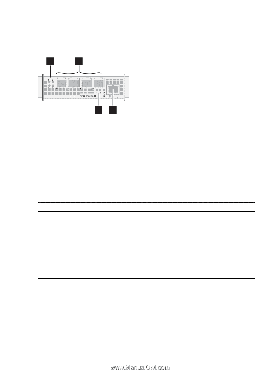
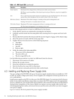
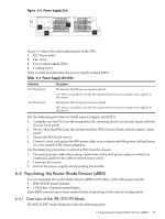
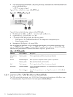
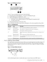
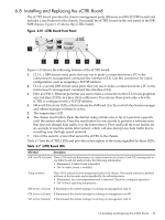
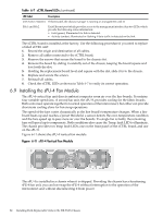
• Four small form-factor SFP GBIC GbE ports, providing a fast link to an IP network for devices on the InfiniBand fabric • An RJ-45 management port. Figure 6-6 shows the front panel of the IPR blade. Figure 6-6 IPR Blade Front Panel 1 2 34 Figure 6-6 shows the following features of the IPR blade: 1. The link/activity LEDs, labelled 1 - 4, one for each labelled port. 2. Gigabit Ethernet ports, labelled Et1 - Et4. 3. 1, 2, and Sys LEDs that provide the following status: • Link status of the combined interfaces in the integrated management port • Overall system status. 4. Management RJ-45 port, with status LEDs. You can replace the SFP GBIC port to configure GbE interface for optional connection types, such as MTRJ, FC, LC, or copper. A status LED is located next to each port. Table 6-5 lists the IPR LEDs and provides a description of the status signalled by these LEDs Table 6-5 IPR Blade LEDs LED Label Link/Activity (1-4) System GbE InfiniBand Color and State Flashing green Description Port is operational and Ethernet packets are detected. Illuminated green Boot sequence is completed and the system is operational. Flashing green Boot sequence initiated and in process. Flashing green Port is operational and Ethernet packets are detected. Illuminated amber Port is operational and a physical link exists between the port and the InfiniBand fabric. Illuminated green Green Port is operational and has a logical connection to the InfiniBand fabric. 6.6.2 Overview of the FCR (Fibre Channel Router) Blade The FCR router blade provides four 1G/2G Fibre Channel ports for optimum InfiniBand over FC communication. Figure 6-7 shows the front panel of the FCR blade. 78 Installing Field-Replaceable Units in the ISR 9XXX Chassis
-
 1
1 -
2
-
3
-
4
-
5
-
6
-
7
-
8
-
9
-
10
-
11
-
12
-
13
-
14
-
15
-
16
-
17
-
18
-
19
-
20
-
21
-
22
-
23
-
24
-
25
-
26
-
27
-
28
-
29
-
30
-
31
-
32
-
33
-
34
-
35
-
36
-
37
-
38
-
39
-
40
-
41
-
42
-
43
-
44
-
45
-
46
-
47
-
48
-
49
-
50
-
51
-
52
-
53
-
54
-
55
-
56
-
57
-
58
-
59
-
60
-
61
-
62
-
63
-
64
-
65
-
66
-
67
-
68
-
69
-
70
-
71
-
72
-
 73
73 -
 74
74 -
 75
75 -
 76
76 -
 77
77 -
 78
78 -
 79
79 -
 80
80 -
 81
81 -
 82
82 -
 83
83 -
84
-
85
-
86
-
87
-
88
-
89
-
90
-
91
-
92
-
93
-
94
-
95
-
96
-
97
-
98
-
99
-
100
-
101
-
102
-
103
-
104
-
105
-
106
-
107
-
108
-
109
-
110
-
111
-
112
-
113
-
114
-
115
-
116
-
117
-
118
-
119
-
120
-
121
-
122
-
123
-
124
-
125
-
126
-
127
-
128
-
129
-
130
-
131
-
132
-
133
-
134
-
135
-
136
-
137
-
138
-
139
-
140
 |
 |