HP Cluster Platform Interconnects v2010 HP Cluster Platform InfiniBand Interco - Page 76
Installing and Replacing Power Supply Units, Table 6-3 sMB Board LEDs
 |
View all HP Cluster Platform Interconnects v2010 manuals
Add to My Manuals
Save this manual to your list of manuals |
Page 76 highlights
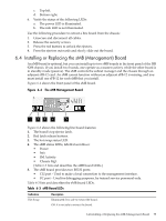
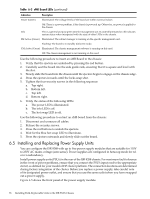
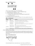
Table 6-3 sMB Board LEDs (continued) Indication Description Power (Green) Illuminated: The voltage levels of the board are within nominal values Off: There is a power problem, if the chassis is powered up. Otherwise, no power is applied to the chassis. Info This is a general purpose green LED for management use. Its state (illuminated or off) indicates system status when interpreted with the state of other LEDs in the chassis. SM Active (Green) Illuminated: The subnet manager is running on the specific management card. Flashing: The board is in standby (failover) mode. CM Active (Green) Illuminated: The chassis management software is running on this card. Off: The chassis management is not running on this card. Use the following procedure to insert an sMB Board to the chassis: 1. Verify that the ejectors are unlocked by pressing the red button. 2. Carefully seat the board into the side guide rails, ensuring that it is square and level with the slot. 3. Slowly slide the board into the chassis until the ejectors begin to engage on the chassis edge. 4. Press the ejectors inwards until the locks snap shut. 5. Tighten the four security screws in the following sequence: a. Top right. b. Bottom left. c. Top left. d. Bottom right. 6. Verify the status of the following LEDs: a. The power LED is illuminated. b. The info LED is off. c. The hot swap LED is off. Use the following procedure to extract an sMB board from the chassis: 1. Disconnect and unsecure all cables. 2. Release the security screws. 3. Press the red buttons to unlock the ejectors. 4. Wait for the blue hot swap LED to illuminate. 5. Press the ejectors outwards and slowly slide out the board. 6.5 Installing and Replacing Power Supply Units You can configure the ISR 9288 with up to five power supply modules that are suitable for 110V to 230V AC mains voltage (auto-sense). Power supplies are configured in hotswap mode for n:1 or n:n redundancy. Install power supply units (PSUs) in the rear of the ISR 9288 chassis. For maximum fault tolerance in the event of power problems, ensure that you connect the PSU's input cord to the appropriate circuit, as defined for your model of HP cluster platform. The connection locations are determined during factory integration of the cluster. Before you replace a power supply, take careful note of its designated power outlet, and ensure that you use the same outlet when you have swapped out a power supply. Figure 6-5 shows the front panel of the power supply module. 76 Installing Field-Replaceable Units in the ISR 9XXX Chassis
-
 1
1 -
2
-
3
-
4
-
5
-
6
-
7
-
8
-
9
-
10
-
11
-
12
-
13
-
14
-
15
-
16
-
17
-
18
-
19
-
20
-
21
-
22
-
23
-
24
-
25
-
26
-
27
-
28
-
29
-
30
-
31
-
32
-
33
-
34
-
35
-
36
-
37
-
38
-
39
-
40
-
41
-
42
-
43
-
44
-
45
-
46
-
47
-
48
-
49
-
50
-
51
-
52
-
53
-
54
-
55
-
56
-
57
-
58
-
59
-
60
-
61
-
62
-
63
-
64
-
65
-
66
-
67
-
68
-
69
-
70
-
 71
71 -
 72
72 -
 73
73 -
 74
74 -
 75
75 -
 76
76 -
 77
77 -
 78
78 -
 79
79 -
 80
80 -
 81
81 -
82
-
83
-
84
-
85
-
86
-
87
-
88
-
89
-
90
-
91
-
92
-
93
-
94
-
95
-
96
-
97
-
98
-
99
-
100
-
101
-
102
-
103
-
104
-
105
-
106
-
107
-
108
-
109
-
110
-
111
-
112
-
113
-
114
-
115
-
116
-
117
-
118
-
119
-
120
-
121
-
122
-
123
-
124
-
125
-
126
-
127
-
128
-
129
-
130
-
131
-
132
-
133
-
134
-
135
-
136
-
137
-
138
-
139
-
140
 |
 |
