HP Cluster Platform Interconnects v2010 HP Cluster Platform InfiniBand Interco - Page 97
Topspin/Mellanox PCI-X HCA
 |
View all HP Cluster Platform Interconnects v2010 manuals
Add to My Manuals
Save this manual to your list of manuals |
Page 97 highlights
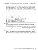
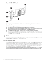
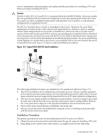
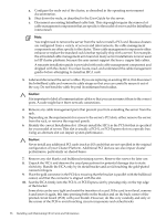
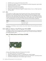
11. Attach the metal bracket to the bulkhead with the retaining screw that you removed in step 6. 12. Close the server chassis and slide it back into the rack. 13. Reinstall any cable management components that you removed in step 4. 14. Reconnect the cables that you disconnected in step 3. 15. You are now ready to cable the card , following the cabling instructions for your model of cluster platform and using the following sequence: a. InfiniBand cables, which must be connected according to the port address specifications for your cluster, as defined in the cluster cabling tables. b. Communications cables, such as CAT-V Ethernet cables c. The server's power cord. d. Begin the node power-up procedures specified for your operating environment. This information is located in the software documentation. When you power up the node and connect a link cable to the system interconnect, the HCA-400 LEDs display the link status, as described in Table 8-1. Table 8-1 HCA-400 Status LEDs LED Indicator Green Status Description The green LED (physical link) displays the following status: • Illuminated: A physical link is present. • Off: No physical link detected. • Flashing: There is a problem with the physical link. Amber The amber LED (logical link) displays the following status: • Illuminated: A logical link is present • Off: No logical link detected. • Flashing: There is a problem with the logical link. After installing the HCA your first task is usually to determine that the its link is correctly cabled and functioning. Consult the interconnect diagnostics chapter to run the appropriate tests that will enable you to verify the operation of the card by its LED status array and by test results. The InfiniBand fabric management software provides a graphical view of the cluster fabric, which should show that the new HCA is present and functioning correctly. See the Voltaire InfiniBand Fabric Management and Diagnostic Guide. Next, boot the operating system and run any diagnostics required to confirm the operation of the interconnect in the cluster, as specified in the operating environment documentation. 8.3 Topspin/Mellanox PCI-X HCA The Topspin/Mellanox PCI-X HCA supports InfiniBand protocols including IPoIB, SDP, SRP, UDAPL and MPI. The Topspin/Mellanox PCI-X HCA is a single data rate (SDR) card with two 4X InfiniBand 10 Gb/s ports and 128 MB local memory. Figure 8-3 shows a Topspin/Mellanox PCI-X HCA. 8.3 Topspin/Mellanox PCI-X HCA 97
-
 1
1 -
2
-
3
-
4
-
5
-
6
-
7
-
8
-
9
-
10
-
11
-
12
-
13
-
14
-
15
-
16
-
17
-
18
-
19
-
20
-
21
-
22
-
23
-
24
-
25
-
26
-
27
-
28
-
29
-
30
-
31
-
32
-
33
-
34
-
35
-
36
-
37
-
38
-
39
-
40
-
41
-
42
-
43
-
44
-
45
-
46
-
47
-
48
-
49
-
50
-
51
-
52
-
53
-
54
-
55
-
56
-
57
-
58
-
59
-
60
-
61
-
62
-
63
-
64
-
65
-
66
-
67
-
68
-
69
-
70
-
71
-
72
-
73
-
74
-
75
-
76
-
77
-
78
-
79
-
80
-
81
-
82
-
83
-
84
-
85
-
86
-
87
-
88
-
89
-
90
-
91
-
 92
92 -
 93
93 -
 94
94 -
 95
95 -
 96
96 -
 97
97 -
 98
98 -
 99
99 -
 100
100 -
 101
101 -
 102
102 -
103
-
104
-
105
-
106
-
107
-
108
-
109
-
110
-
111
-
112
-
113
-
114
-
115
-
116
-
117
-
118
-
119
-
120
-
121
-
122
-
123
-
124
-
125
-
126
-
127
-
128
-
129
-
130
-
131
-
132
-
133
-
134
-
135
-
136
-
137
-
138
-
139
-
140
 |
 |
