HP Cluster Platform Interconnects v2010 HP Cluster Platform InfiniBand Interco - Page 82
Installing the sFU-4 Fan Module, Table 6-7 sCTRL Board LEDs, sFU-4 VerticalFan Module
 |
View all HP Cluster Platform Interconnects v2010 manuals
Add to My Manuals
Save this manual to your list of manuals |
Page 82 highlights
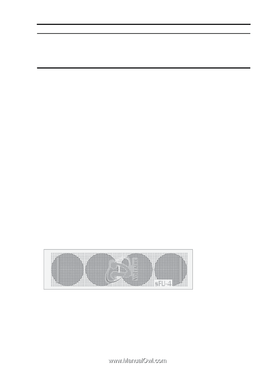
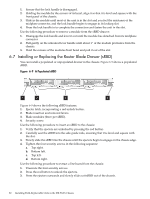
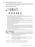
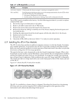
Table 6-7 sCTRL Board LEDs (continued) LED label Description CM Active 2 (Green) If illuminated, the chassis manager is running on management card #2 Eth 1 and Eth 2 Each Ethernet port (which provides access to the management interface) has two LEDs, which provide the following status information: • Link (green): Illuminated if a link is detected. • Activity (amber): Illuminated or flashing if data traffic is detected on the link. The sCTRL board is installed at the factory. Use the following procedure if you need to replace a failed sCTRL unit: 1. Record the origin and destination of all cables. 2. Remove all cables connected to the sCTRL board. 3. Remove the screws that secure the board to the chassis slot. 4. Remove the board by sliding it carefully out of the chassis, keeping the board square and level with the slot. 5. Holding the replacement board level and square with the slot, slide it in to the chassis. 6. Replace and secure the screws. 7. Reinstall all cables. 8. Check the sCTRL LEDs as shown in Table 6-7 to verify its correct operation. 6.9 Installing the sFU-4 Fan Module The sFU-4 vertical fan unit directs ambient computer room air over the line boards. It contains four variable speed fans. A second fan unit, the sFU-8, provides cooling for the fabric boards. Both units must operate together for normal operation of the interconnect, but either can provide short-term cooling alone for hot-swap operations. The speed of the fans varies dynamically as the line board's temperature changes. When a line board heats up and reaches a preset threshold, a sensor detects the over-temperature condition and the fans speed up to pass more air over the boards. If a single fan is faulty, the remaining fans will speed up to compensate. Both conditions also cause the Temp. fault LED to illuminate. The chassis provides two temp fault LEDs; one on the front panel of the sCTRL board, and one on the sFU-8. Figure 6-11 shows the sFU-4 vertical fan module Figure 6-11 sFU-4 Vertical Fan Module The sFU-4 is installed in a chassis when it is shipped. Providing the chassis has a functioning sFU-8 fan unit, you can hot-swap the sFU-4 without interruption to the operation of the interconnect and without disconnecting it from power. 82 Installing Field-Replaceable Units in the ISR 9XXX Chassis
-
 1
1 -
2
-
3
-
4
-
5
-
6
-
7
-
8
-
9
-
10
-
11
-
12
-
13
-
14
-
15
-
16
-
17
-
18
-
19
-
20
-
21
-
22
-
23
-
24
-
25
-
26
-
27
-
28
-
29
-
30
-
31
-
32
-
33
-
34
-
35
-
36
-
37
-
38
-
39
-
40
-
41
-
42
-
43
-
44
-
45
-
46
-
47
-
48
-
49
-
50
-
51
-
52
-
53
-
54
-
55
-
56
-
57
-
58
-
59
-
60
-
61
-
62
-
63
-
64
-
65
-
66
-
67
-
68
-
69
-
70
-
71
-
72
-
73
-
74
-
75
-
76
-
 77
77 -
 78
78 -
 79
79 -
 80
80 -
 81
81 -
 82
82 -
 83
83 -
 84
84 -
 85
85 -
 86
86 -
 87
87 -
88
-
89
-
90
-
91
-
92
-
93
-
94
-
95
-
96
-
97
-
98
-
99
-
100
-
101
-
102
-
103
-
104
-
105
-
106
-
107
-
108
-
109
-
110
-
111
-
112
-
113
-
114
-
115
-
116
-
117
-
118
-
119
-
120
-
121
-
122
-
123
-
124
-
125
-
126
-
127
-
128
-
129
-
130
-
131
-
132
-
133
-
134
-
135
-
136
-
137
-
138
-
139
-
140
 |
 |