HP Cluster Platform Interconnects v2010 HP Cluster Platform InfiniBand Interco - Page 61
Assembling9XXX Rails, Caution, Working at the front of the rack
 |
View all HP Cluster Platform Interconnects v2010 manuals
Add to My Manuals
Save this manual to your list of manuals |
Page 61 highlights
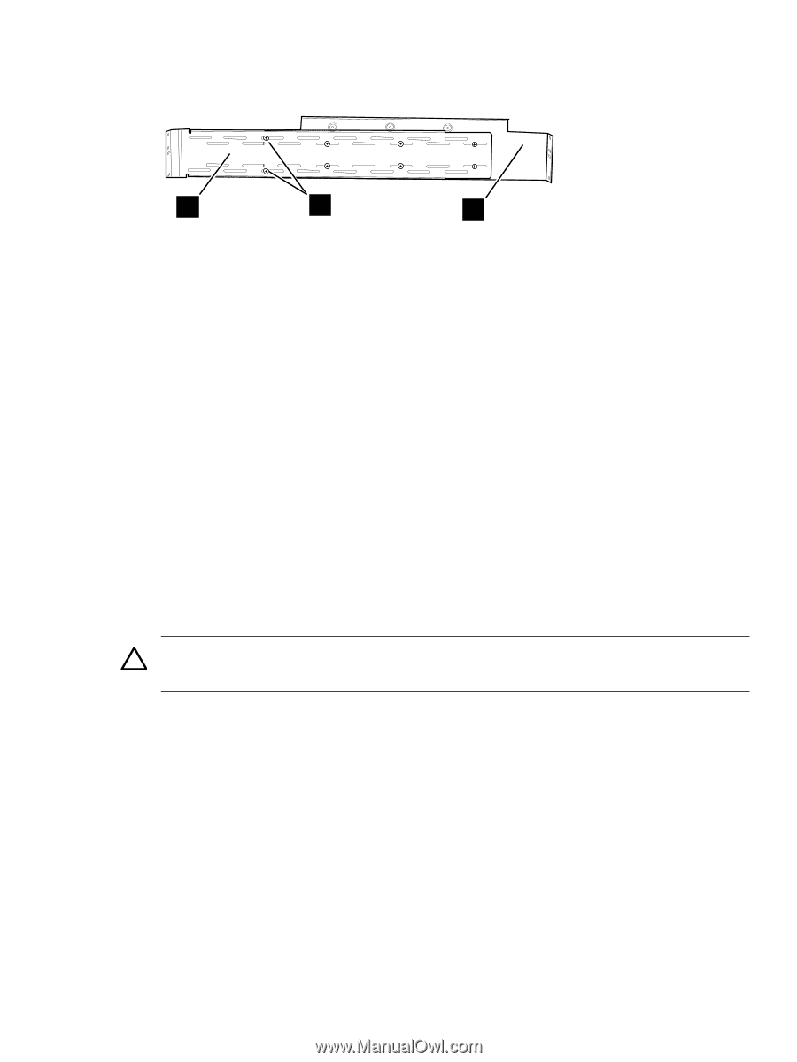
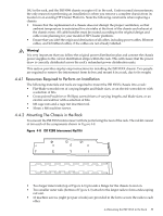
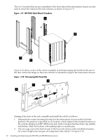
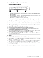
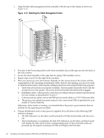
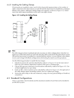
3. Assemble each pair of rails, as shown in Figure 4-11. Figure 4-11 Assembling 9XXX Rails 1 2 3 a. Place the slotted rail (callout 1 in Figure 4-11) on the outside of the larger rail (callout 3 in Figure 4-11) b. Secure the slotted rail loosely, using eight of the machine screws provided. Two of these screws are shown by (callout 2 in Figure 4-11) c. Repeat Step 3a and 3b for the second rail assembly. 4. Place the left assembly in the rack, and adjust its length (by telescoping the unit) until the mounting flanges are against the face of the rack columns, at the mounting location. (See callout 2 in Figure 4-10). 5. Secure the assembly to the rack by using four M6 machine screws, two per mounting flange, at the front and rear columns. (See callout 3 in Figure 4-10). 6. Tighten the eight machine screws that you inserted in the assembly in Step 3b, to lock the telescoping assembly in place. 7. Repeat Step 4 through Step 6 for the right rail assembly. Use the following procedure to mount the chassis on the assembled rail kit: 1. If you are replacing an interconnect chassis, bring the cluster to an appropriate state, as described in the operating environment documentation. 2. Working at the front of the switch, remove the pull handles from the long L-brackets that are attached to the sides of the chassis. The handles are not required. 3. Working at the front of the rack, clip 6 M6 cage nuts into the rear of the rack columns, as shown by callout 3 in Figure 4-9. Caution: The chassis is heavy and the next step requires two people. 4. Place the chassis on the rail kit support flange, and slide the chassis into the rack, so that the L-brackets are flush with the rack columns. 5. Secure the chassis to the rail kit by using three machine screws through each of the the larger rails, using the holes identified by callout 4 in Figure 4-10, four a total of six screws. 6. Secure the L-brackets to the front rack columns by using 6 M6 machine screws, as shown by callout 4 in Figure 4-9. Use the following procedure to attach the cable management hooks to the racks: 4.4 Mounting the ISR 9XXX in the Rack 61
-
 1
1 -
2
-
3
-
4
-
5
-
6
-
7
-
8
-
9
-
10
-
11
-
12
-
13
-
14
-
15
-
16
-
17
-
18
-
19
-
20
-
21
-
22
-
23
-
24
-
25
-
26
-
27
-
28
-
29
-
30
-
31
-
32
-
33
-
34
-
35
-
36
-
37
-
38
-
39
-
40
-
41
-
42
-
43
-
44
-
45
-
46
-
47
-
48
-
49
-
50
-
51
-
52
-
53
-
54
-
55
-
 56
56 -
 57
57 -
 58
58 -
 59
59 -
 60
60 -
 61
61 -
 62
62 -
 63
63 -
 64
64 -
 65
65 -
 66
66 -
67
-
68
-
69
-
70
-
71
-
72
-
73
-
74
-
75
-
76
-
77
-
78
-
79
-
80
-
81
-
82
-
83
-
84
-
85
-
86
-
87
-
88
-
89
-
90
-
91
-
92
-
93
-
94
-
95
-
96
-
97
-
98
-
99
-
100
-
101
-
102
-
103
-
104
-
105
-
106
-
107
-
108
-
109
-
110
-
111
-
112
-
113
-
114
-
115
-
116
-
117
-
118
-
119
-
120
-
121
-
122
-
123
-
124
-
125
-
126
-
127
-
128
-
129
-
130
-
131
-
132
-
133
-
134
-
135
-
136
-
137
-
138
-
139
-
140
 |
 |