HP Cluster Platform Interconnects v2010 HP Cluster Platform InfiniBand Interco - Page 90
Connecting to FCR FC Ports, 7.3 Chassis Administrative Connections
 |
View all HP Cluster Platform Interconnects v2010 manuals
Add to My Manuals
Save this manual to your list of manuals |
Page 90 highlights
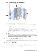
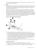
7.2.2 Connecting to FCR FC Ports Use the following procedure to connect a cable to the Fibre Channel port: 1. Connect the small form-factor FC 1G/2G 850nm LC transceiver connector to the FC port on the FCR module. 2. Connect the other end of the cable to the appropriate device. 7.3 Chassis Administrative Connections You make the initial CLI connection to a chassis through a PC connected to a serial port. This connection enables you to perform basic configuration, such as setting up IP addresses. When the IP address is configured, you can connect to a chassis over the Ethernet, and use the Web-based management interface. 7.3.1 Cabling the ISR 9024 Management Connections The ISR 9024 management ports are located on the front panel. The following ports are provided: 1. For an internally managed ISR 9024, connect a single Ethernet cable to the connector located either on the rear panel or on the front panel. 2. For an internally managed ISR 9024, plug the DB-9 adapter into the mini-USB port and connect the DB-9 adapter to a CLI console via a serial cable (not provided). 3. For an externally managed ISR 9024, connect the I²C cable (not provided) between the DB-9 connector and the management console. Use the following procedure to connect to the management port Ethernet Interface: 1. See the Ethernet Cabling Tables to determine where the management port connects to an in-rack ProCurve switch. 2. Connect the end of the management cable with the RJ-45 connector to the management port. 3. Connect the end of the cable with Ethernet connector to the appropriate ProCurve switch port. 7.3.2 Cabling the ISR 9096 and the ISR 9288 Management Connections The ISR 9096 and the ISR 9288 management ports are located on the front panel of the sCTRL board. The following ports are provided: • A DB9 serial interface for local console access. Use this serial port to connect to a PC running terminal emulation software. You can use this connection to run the management CLI over a Telnet login. • A 10/100 Ethernet interface for network access. Connect this port to an IP network. You can use this connection either to run a CLI (via Telnet) or the GUI (via a Web browser or Java Web client). • A diagnostic I²C interface is provided for the use of technical support personnel only. If you choose not to use the built-in software interfaces, you can use a third party SNMP manager. If the configuration calls for out-of-band management, you must connect the management network to the corresponding management ports on the rear of the chassis. You can connect both types of management network simultaneously. Two Ethernet connectors and two serial ports are provided. These ports correspond to the sMB boards on the right and left sides of the chassis front. Connect one or more Ethernet cables to the RJ-45 connectors on the interconnect that correspond to installed sMB boards. Connect one or more serial cables to the DB-9 connectors in a similar manner. Consult the Ethernet Network Cabling Tables for information on connecting the InfiniBand interconnect to a ProCurve switch located in the Cluster. Use modular, RJ-45, straight-through UTP cables to connect the 10/100 Fast Ethernet ports to end systems. Use modular, RJ-45 cross-connect cables to connect to external switches and routers. 90 Cabling the Interconnect
-
 1
1 -
2
-
3
-
4
-
5
-
6
-
7
-
8
-
9
-
10
-
11
-
12
-
13
-
14
-
15
-
16
-
17
-
18
-
19
-
20
-
21
-
22
-
23
-
24
-
25
-
26
-
27
-
28
-
29
-
30
-
31
-
32
-
33
-
34
-
35
-
36
-
37
-
38
-
39
-
40
-
41
-
42
-
43
-
44
-
45
-
46
-
47
-
48
-
49
-
50
-
51
-
52
-
53
-
54
-
55
-
56
-
57
-
58
-
59
-
60
-
61
-
62
-
63
-
64
-
65
-
66
-
67
-
68
-
69
-
70
-
71
-
72
-
73
-
74
-
75
-
76
-
77
-
78
-
79
-
80
-
81
-
82
-
83
-
84
-
 85
85 -
 86
86 -
 87
87 -
 88
88 -
 89
89 -
 90
90 -
 91
91 -
 92
92 -
 93
93 -
 94
94 -
 95
95 -
96
-
97
-
98
-
99
-
100
-
101
-
102
-
103
-
104
-
105
-
106
-
107
-
108
-
109
-
110
-
111
-
112
-
113
-
114
-
115
-
116
-
117
-
118
-
119
-
120
-
121
-
122
-
123
-
124
-
125
-
126
-
127
-
128
-
129
-
130
-
131
-
132
-
133
-
134
-
135
-
136
-
137
-
138
-
139
-
140
 |
 |