HP Cluster Platform Interconnects v2010 HP Cluster Platform InfiniBand Interco - Page 44
Mounting the ISR 9024 S/D in the Rack, A documentation CD containing ISR 9024 S/D documentation.
 |
View all HP Cluster Platform Interconnects v2010 manuals
Add to My Manuals
Save this manual to your list of manuals |
Page 44 highlights
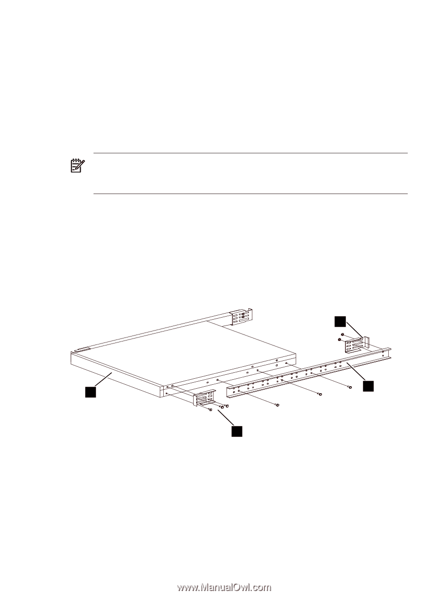
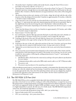
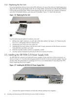
8. Open the small box (callout 4 in Figure 3-4) and verify its contents against the packing list as follows. Some parts are optional, and might not be included in all shipments: a. Verify that the chassis is the correct configuration; internally managed or externally managed. b. Identify the rail kit consisting of: 1. Four angle brackets. 2. Two chassis-mounted rails. c. If an internally managed unit, verify that a management cable adapter is present. d. At least one power cable, depending on the configuration (callouts 1 and 5 in Figure 3-4). e. A documentation CD containing ISR 9024 S/D documentation. f. Quick start documentation (callout 7 in Figure 3-4). Note: For HP Cluster Platform, refer only to the HP documentation for installation and configuration instructions. Perform the preceding steps in reverse order to repack a chassis for shipping, ensuring that the chassis is secure in the shock-absorbing materials. Do not reuse any damaged packaging, contact your HP sales and service representative if you are unsure about return shipping requirements. 3.3 Mounting the ISR 9024 S/D in the Rack You mount the ISR 9024 S/D interconnect with its ports facing towards the rear of the rack. Figure 3-5 shows the mounting kit in use. Figure 3-5 The ISR 9024 S/D Rack Kit 2 3 4 1 Use the following procedure to mount the chassis in the rack: 1. If you are replacing an interconnect chassis, bring the cluster to an appropriate state, as described in the operating environment documentation. HP recommends that you power up the chassis before installing it in the rack to ensure that all status LEDs indicate that components and ports function correctly. 2. Determine the correct mounting location for the interconnect in your model of cluster platform. The position is specified as a U-location, which relates to the marked locations on the vertical columns an a HP 10000-series rack. Each U-location has three holes; top, middle, and bottom. This rack kit uses the top and bottom hole of the specified location. mark the location with masking tape or a marker pen. 44 Installing and Maintaining the ISR 9024 S/D Interconnect (RoHS Compliant)
-
 1
1 -
2
-
3
-
4
-
5
-
6
-
7
-
8
-
9
-
10
-
11
-
12
-
13
-
14
-
15
-
16
-
17
-
18
-
19
-
20
-
21
-
22
-
23
-
24
-
25
-
26
-
27
-
28
-
29
-
30
-
31
-
32
-
33
-
34
-
35
-
36
-
37
-
38
-
 39
39 -
 40
40 -
 41
41 -
 42
42 -
 43
43 -
 44
44 -
 45
45 -
 46
46 -
 47
47 -
 48
48 -
 49
49 -
50
-
51
-
52
-
53
-
54
-
55
-
56
-
57
-
58
-
59
-
60
-
61
-
62
-
63
-
64
-
65
-
66
-
67
-
68
-
69
-
70
-
71
-
72
-
73
-
74
-
75
-
76
-
77
-
78
-
79
-
80
-
81
-
82
-
83
-
84
-
85
-
86
-
87
-
88
-
89
-
90
-
91
-
92
-
93
-
94
-
95
-
96
-
97
-
98
-
99
-
100
-
101
-
102
-
103
-
104
-
105
-
106
-
107
-
108
-
109
-
110
-
111
-
112
-
113
-
114
-
115
-
116
-
117
-
118
-
119
-
120
-
121
-
122
-
123
-
124
-
125
-
126
-
127
-
128
-
129
-
130
-
131
-
132
-
133
-
134
-
135
-
136
-
137
-
138
-
139
-
140
 |
 |